Bicycle component and mounting structure for bicycle component

a technology for bicycle components and mounting structures, which is applied in the direction of cycle frames, bicycle equipment, vehicle components, etc., can solve the problems of gap formed between the side plates and the mounting portion, and the motor unit may rattle on the two side plates, and achieve the effect of easy mounting and easy engagement of the tool engagement portion

Active Publication Date: 2019-02-07
SHIMANO INC
View PDF0 Cites 6 Cited by
  • Summary
  • Abstract
  • Description
  • Claims
  • Application Information

AI Technical Summary

Benefits of technology

[0015]In accordance with a tenth aspect of the present disclosure, the bicycle component according to any one of the second to ninth aspects is configured so that at least one of the first member or the second member further includes a tool engagement portion that is engageable with a tool. In accordance with the tenth aspect, the tool allows the bicycle component to be easily mounted on the frame.
[0016]In accordance with an eleventh aspect of the present disclosure, the bicycle component according to the tenth aspect is configured so that the tool engagement portion is defined by at least one of an inner circumferential portion or an outer circumferential portion of the first member. In accordance with the eleventh aspect, the tool can easily engage the tool engagement portion.

Problems solved by technology

In the motor unit described above, manufacturing tolerances may result in gaps formed between the side plates and the mounting portion, which are fastened by the bolts.
In this case, the motor unit may rattle on the two side plates when the bicycle is traveling.

Method used


Image

  • Bicycle component and mounting structure for bicycle component
  • Bicycle component and mounting structure for bicycle component
  • Bicycle component and mounting structure for bicycle component

Examples


first embodiment

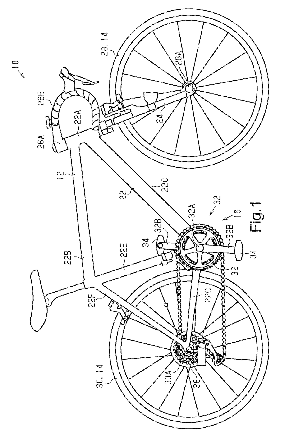
[0062]A bicycle 10 including a bicycle component 40 in accordance with a first embodiment will now be described with reference to FIGS. 1 to 9. The bicycle 10 is a road bike. However, the present disclosure is also applicable to a bicycle other than a road bike such as a mountain bike and a city bike. The vertical direction of the bicycle 10 is the vertical direction in a state in which the bicycle 10 is ridable and held upright on a level surface. The sideward direction of the bicycle 10 is the sideward direction as viewed in the traveling direction of the bicycle 10 in a state in which the bicycle 10 is ridable and held upright on a level surface.

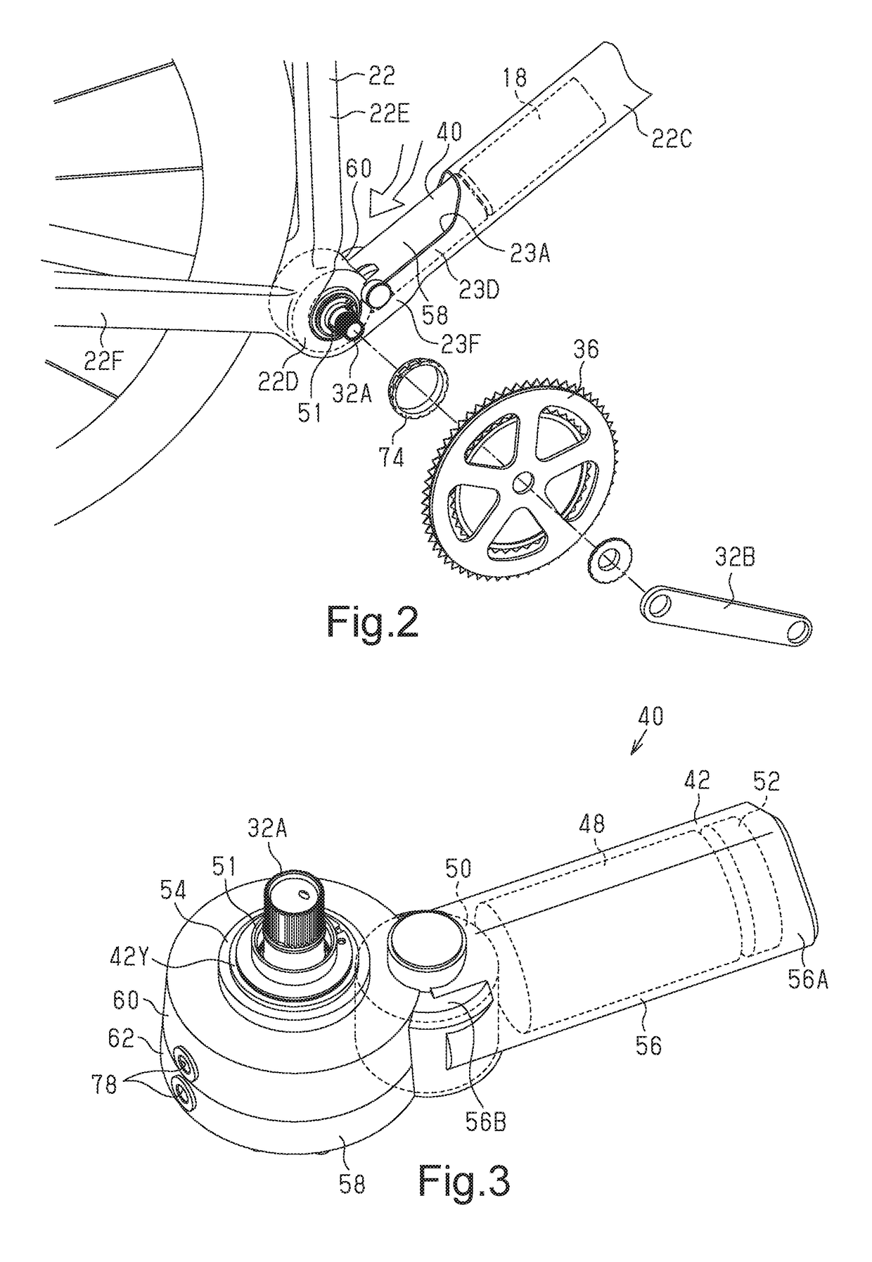
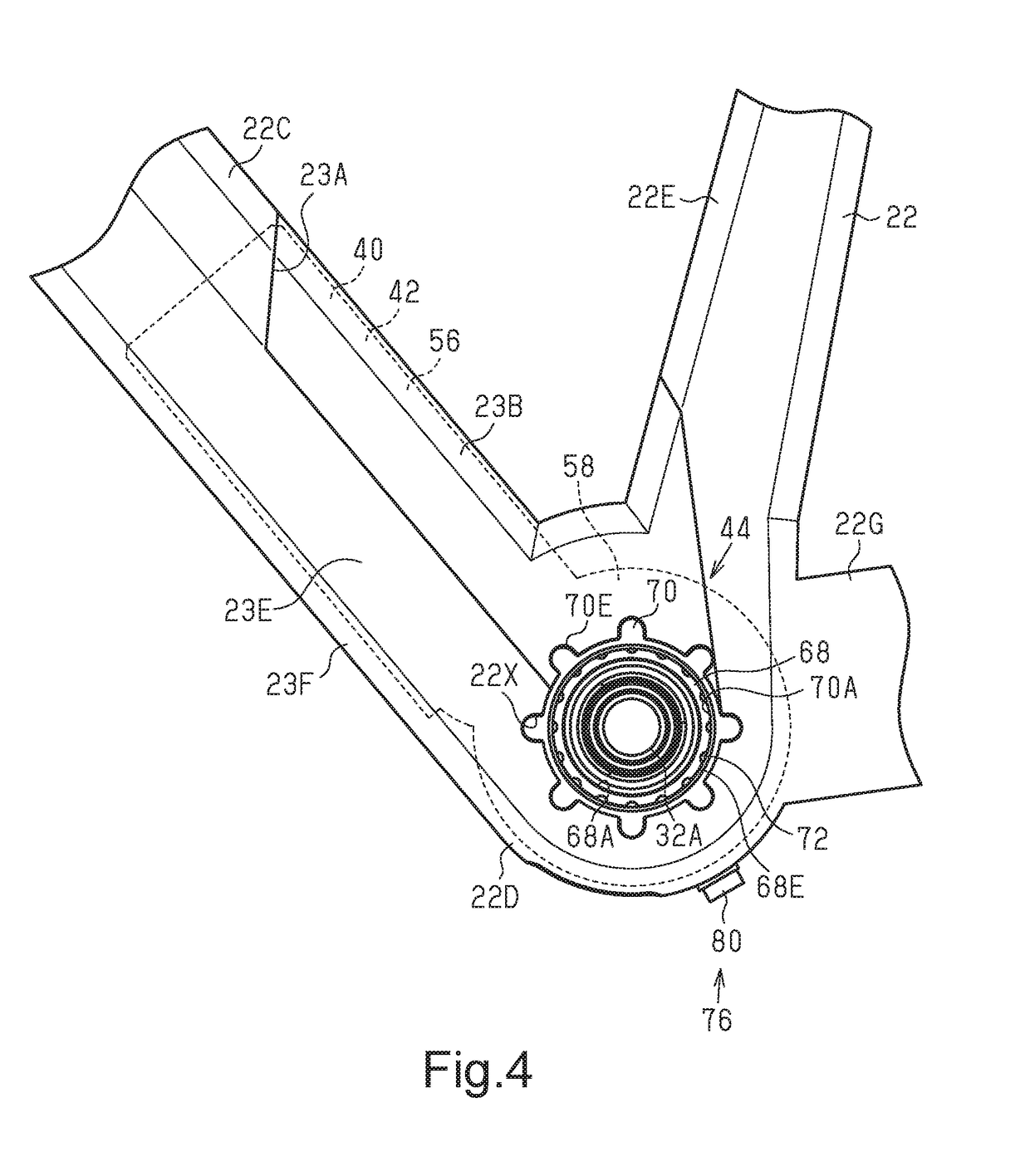
[0063]As shown in FIGS. 1 and 2, the bicycle 10 includes a bicycle body 12, a pair of wheels 14, a drive mechanism 16, a battery 18 and the bicycle component40. In the present embodiment, the bicycle component 40 is a bicycle drive unit. The bicycle body 12 includes a frame 22, a front fork 24 and a handlebar 26B. The front fork 24 is con...

second embodiment

[0091]A bicycle component 40 in accordance with a second embodiment will now be described with reference to FIG. 10. The bicycle component 40 in accordance with the second embodiment differs from the bicycle component 40 in accordance with the first embodiment only in the position where the bicycle component 40 is mounted on the frame 22. Otherwise, the bicycle component 40 in accordance with the second embodiment is the same as the bicycle component 40 in accordance with the first embodiment. Thus, same reference numerals are given to those components that are the same as the corresponding components of the first embodiment. Such components will not be described in detail. In the present embodiment, at least part of the first accommodation portion 56 of the housing 42 is accommodated in the seat tube 22E.

[0092]As shown in FIG. 10, the first accommodation portion 56 of the housing 42 is accommodated in at least part of the seat tube 22E, and the second accommodation portion 58 of th...

third embodiment

[0094]A bicycle component 92 in accordance with a third embodiment will now be described with reference to FIGS. 11 and 12. The bicycle component 92 in accordance with the third embodiment differs from the bicycle component 40 in accordance with the first embodiment only in that the bicycle component 92 is provided outside the frame 22. Otherwise, the bicycle component 92 in accordance with the third embodiment is the same as the bicycle component 40 in accordance with the first embodiment. Thus, same reference numerals are given to those components that are the same as the corresponding components of the first embodiment. Such components will not be described in detail.

[0095]As shown in FIG. 11, the frame 22 is provided with a bracket 100 for mounting the bicycle component 92. The bracket 100 is connected to the frame 22 at the lower end of the down tube 22C, the lower end of the seat tube 22E and the front end of the chain stay 22G.

[0096]At least part of the bicycle component 92 i...


PUM


Abstract

A bicycle component includes a housing that supports a crankshaft of a bicycle and a first mounting portion that mounts the housing on a frame of the bicycle. The first mounting portion is configured to apply force to the housing and the frame that moves the housing and the frame away from each other.

Description

CROSS-REFERENCE TO RELATED APPLICATIONS[0001]This application claims priority to Japanese Patent Application No. 2017-151595, filed on Aug. 4, 2017, and Japanese Patent Application No. 2017-220331 filed on Nov. 15, 2017. The entire disclosures of Japanese Patent Application Nos. 2017-151595 and 2017-220331 are hereby incorporated herein by reference.BACKGROUNDField of the Invention[0002]The present invention generally relates to a bicycle component and a mounting structure for a bicycle component.Background Information[0003]A drive unit is a bicycle component that includes a motor that assists propulsion of a bicycle. One example of such a drive unit is disclosed in Japanese Patent No. 4416620 (hereinafter patent document 1), which describes a motor unit including a mounting portion that allows for mounting on a bracket provided on a frame of a bicycle. The mounting portion is inserted between two side plates of the bracket. The side plates and the mounting portion are fastened by b...

Claims


Application Information

Patent Timeline
Patent Type & Authority Applications(United States)
IPC IPC(8): B62K19/34B62M6/55
CPCB62K19/34B62M6/55B62M6/90
Inventor NODA, SHINICHIROFUJIWARA, TAKAAKITAGAYA, KENSUKE
Owner SHIMANO INC
Why Eureka
Try Eureka