Method and apparatus for accessing and activating accessory functions of electronic circuit breakers

a technology of electronic circuit breakers and accessories, applied in the direction of emergency protective arrangements for limiting excess voltage/current, protective switch details, protective switch operating/release mechanisms, etc., can solve the problem that the operator cannot install these additional functions in the field

Inactive Publication Date: 2007-11-27
GENERAL ELECTRIC CO
View PDF240 Cites 21 Cited by
  • Summary
  • Abstract
  • Description
  • Claims
  • Application Information

AI Technical Summary

Problems solved by technology

The operator could not install thes

Method used


Image

  • Method and apparatus for accessing and activating accessory functions of electronic circuit breakers
  • Method and apparatus for accessing and activating accessory functions of electronic circuit breakers
  • Method and apparatus for accessing and activating accessory functions of electronic circuit breakers

Examples


Embodiment Construction

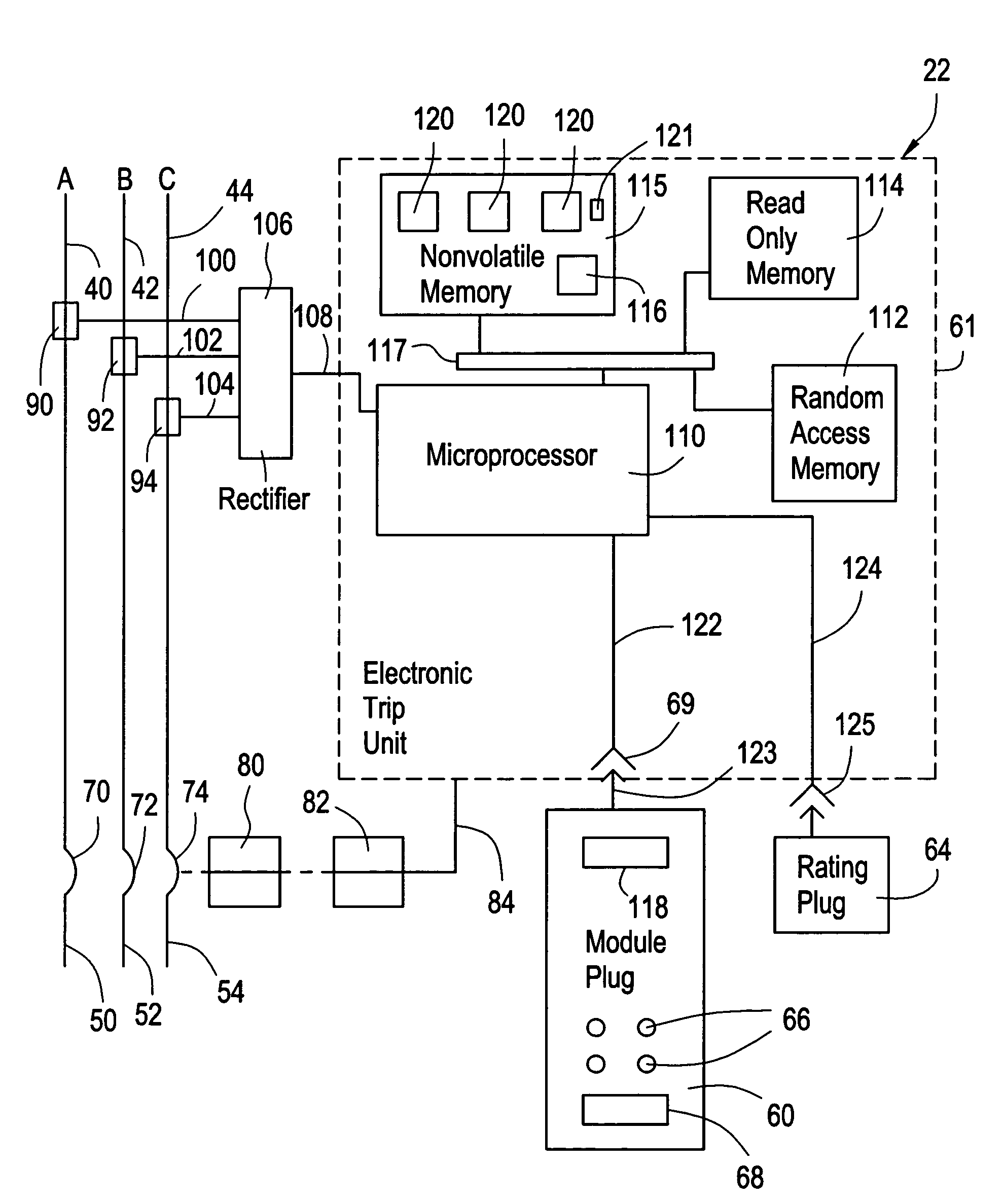
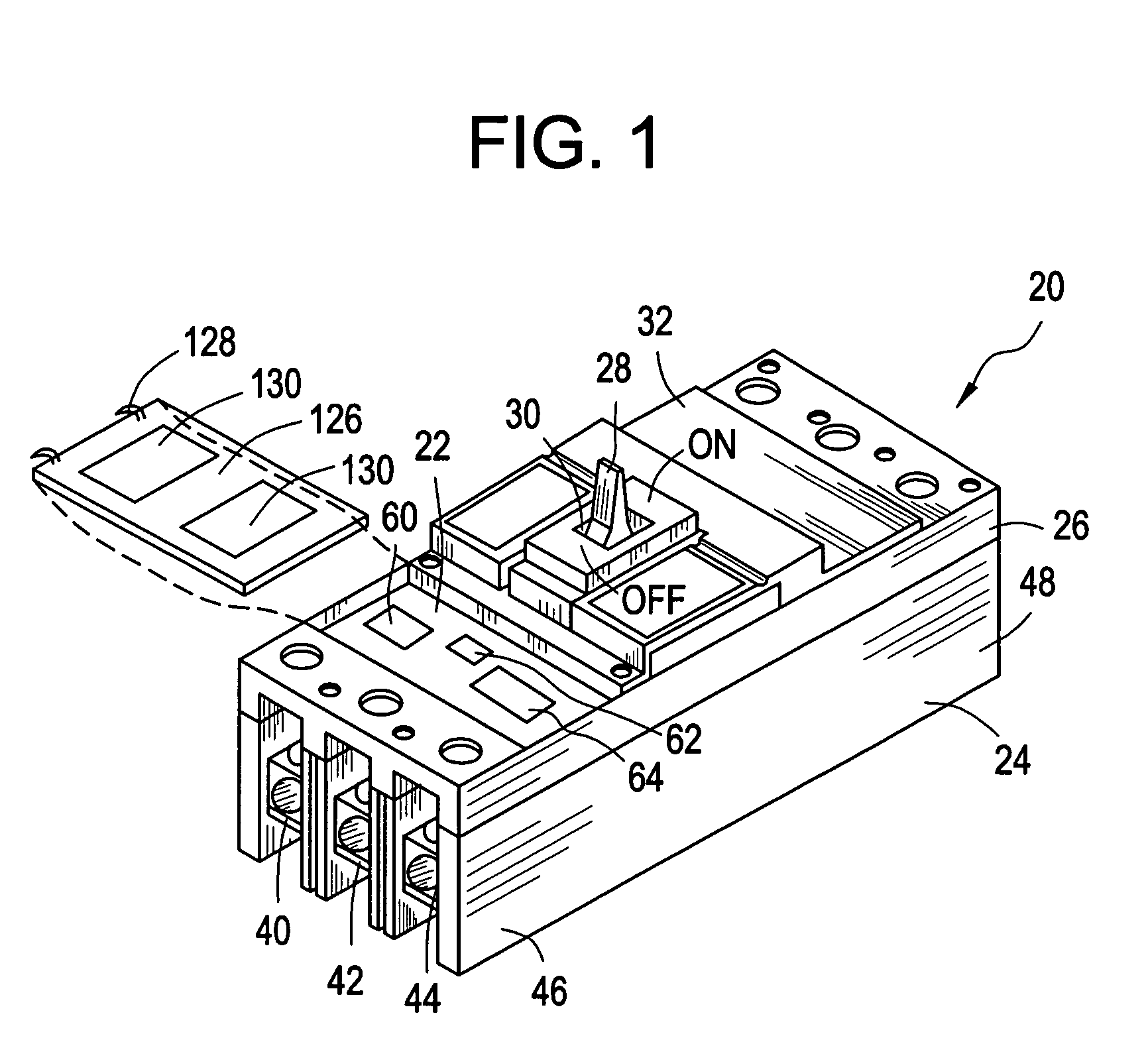
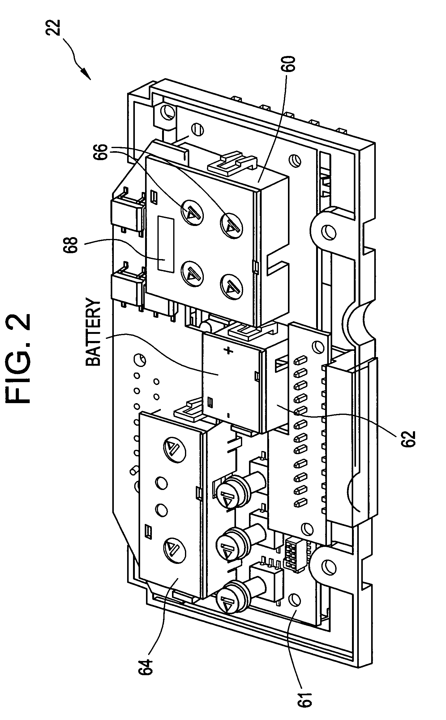
[0015]Referring to FIG. 1, a molded case circuit breaker 20 employing an electronic trip unit 22 is generally shown. Circuit breakers of this type have an insulated case 24 and a mid-cover 26 that house the components of circuit breaker 20. A handle 28 extending through an aperture 30 of a cover 32 gives the operator the ability to turn circuit breaker 20“on”, which allows electricity to flow through circuit breaker 20, turn circuit breaker 20“off”, which prevents electricity from flowing through circuit breaker 20, or “reset” circuit breaker 20 after a fault. A plurality of electrically conducting load side contact straps (load straps) 40, 42, and 44 at a load side 46 of circuit breaker 20 extend within case 24. Line side contact straps 50, 52, 54 (shown on FIG. 3) are located on a line side 48 of circuit breaker and also extend within case 24. Circuit breaker 20 illustrates a typical three-phase configuration, however, the present disclosure is not limited to this configuration bu...


PUM


Abstract

An electronic trip unit for a circuit breaker includes a programmed microprocessor and a module plug in removable signal communication with the microprocessor. The module plug includes a program identifier. The microprocessor recognizes the program identifier and accesses a program of a plurality of programs external to the module plug based on the program identifier. The microprocessor responds to the program to perform a function identified by the module plug. The function identifiable by the module plug includes a communications function, a load monitoring function, a non-tripping ground fault alarm function, a flag function, or any combination thereof.

Description

CROSS-REFERENCE TO RELATED APPLICATIONS[0001]This application is a continuation-in-part application of U.S. application Ser. No. 09 / 682,512 filed Sep. 12, 2001, now U.S. Pat. No. 6,678,135, which is hereby incorporated by reference in its entirety.BACKGROUND OF THE INVENTION[0002]Electronic trip units (trip units) for actuating the separable contacts in a circuit breaker are well known. An electronic trip unit typically comprises voltage and current sensors that provide analog signals indicative of current or voltage in a power distribution circuit. The analog signals are converted by an A / D (analog / digital) converter to digital signals that are processed by a microcontroller. The trip unit further includes RAM (random access memory), ROM (read only memory) and EEPROM (electronic erasable programmable read only memory) all of which interface with the microcontroller. The ROM includes trip unit application code, e.g., main functionality trip setting values, including initializing par...

Claims


Application Information

Patent Timeline
IPC IPC(8): H02H7/00H01H71/02H01H71/12H01H71/74H02H3/00
CPCH02H3/006H01H71/0228H01H71/7409H01H71/123
Inventor TIGNOR, MICHAEL S.BRADLEY, MICHAEL B.WAMBOLT, LEEANNEBUTLAND, GEOFFREY F.THOMAS, MICHAEL H.RAJOTTE, PAUL
Owner GENERAL ELECTRIC CO
Why Eureka
Try Eureka