
Combined computer security lock and security cable

a technology of which is applied in the field of combination computer security lock and security cable, can solve the problems of tangling of the cable, shortening the effective length, and attracting thieves to the notebook computer

Inactive Publication Date: 2007-12-04
LU WEI HSIANG +1
View PDF13 Cites 27 Cited by
  • Summary
  • Abstract
  • Description
  • Claims
  • Application Information

AI Technical Summary

Benefits of technology

[0010]An object of the present invention is to provide a computer security lock with a novel and simple latch mechanism for engaging a slot in a computer housing.
[0011]Another object of the present invention is to provide a combined computer security lock and security cable that has a cable capable of swivelling to provide flexibility and convenience in attaching the cable to a fixed anchor and to reduce an incidence of entanglement.

Problems solved by technology

However, the portability of the notebook computer gives rise to concerns that the notebook computer is a tempting target for thieves.
However, these locks require using a key to secure the lock to the computer, and have to rely on a rotating cam mechanism to move the hook(s) behind the sidewall.
Consequently, conventional notebook computer security cables either require a separate adaptor for connection to the computer, or require that a key be inserted into the lock and rotated to secure the lock to the computer, or require complex rotating cam mechanisms for attachment to the computer.
In addition, many security cable locks require the use of washers or spacers to adjust the length of the lock bar for a snug fit against the sidewall of the computer housing, or use a complex arrangement of springs for the same purpose.
Further, conventional notebook computer security cables are rigidly attached to the lock housing, thereby shortening the effective length of the cable, limiting the choice of anchors to secure the cable thereto, and frequently resulting in tangling of the cable.

Method used


Image

  • Combined computer security lock and security cable
  • Combined computer security lock and security cable
  • Combined computer security lock and security cable

Examples


Embodiment Construction

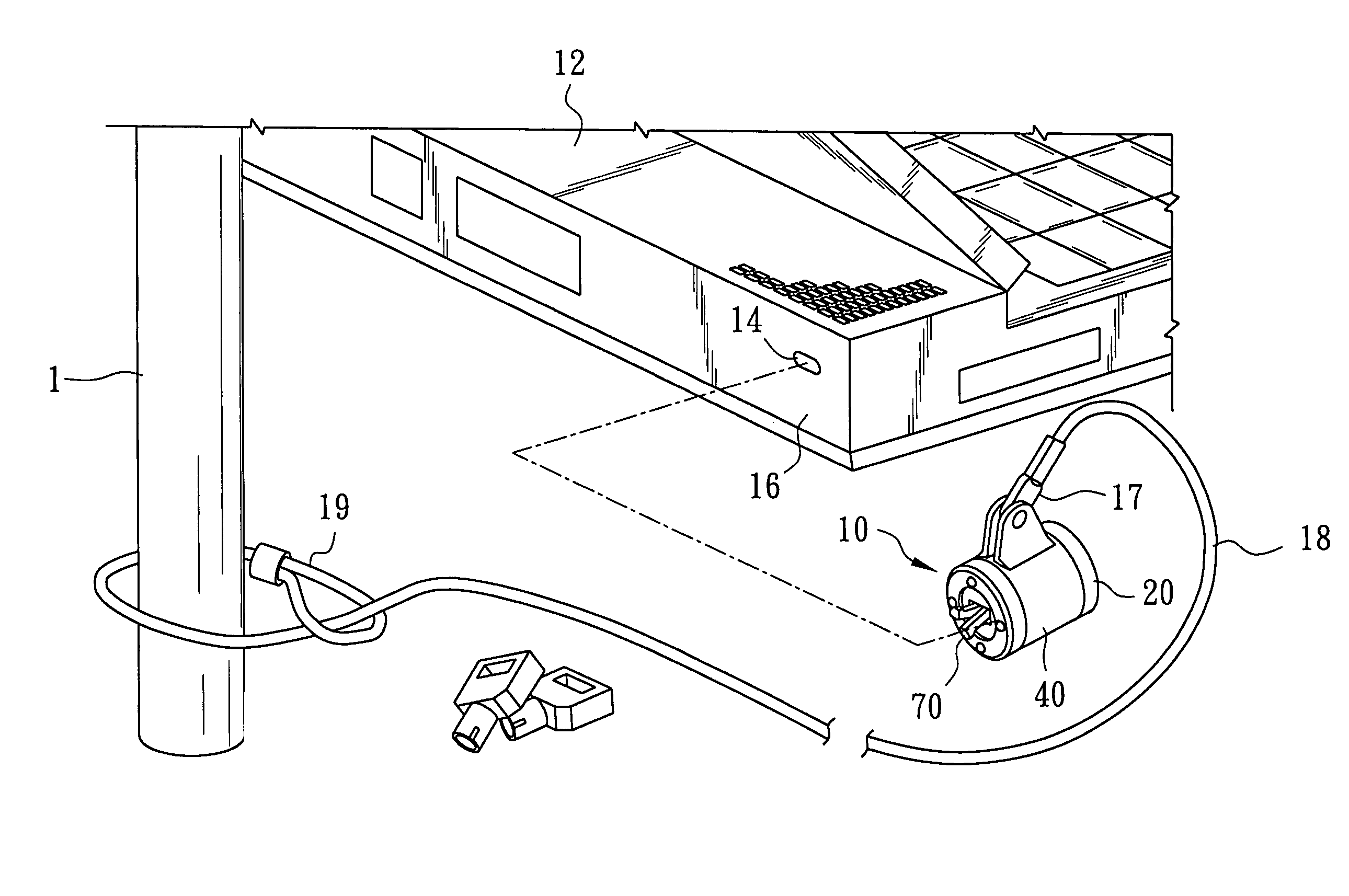
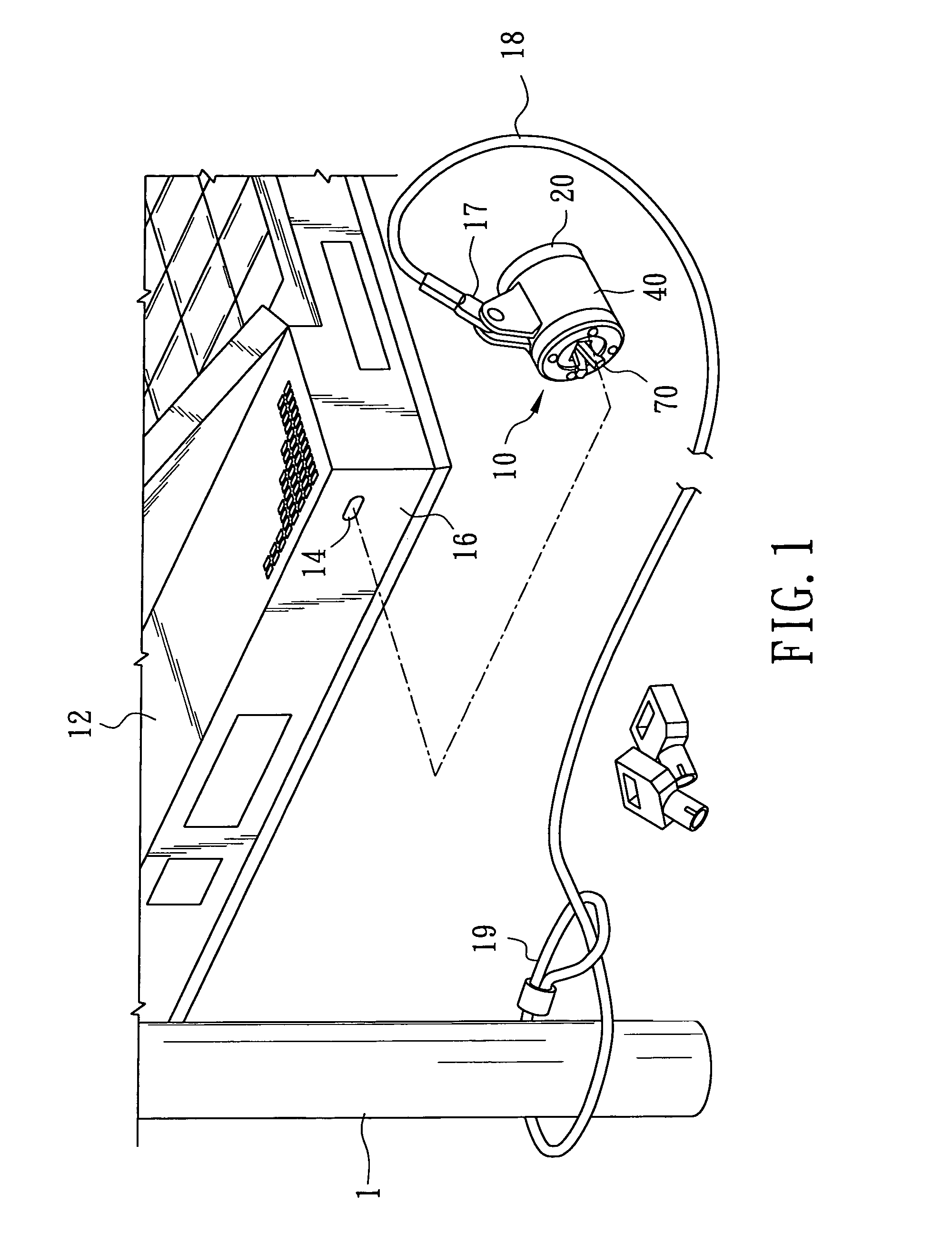
[0019]Referring to FIG. 1, there is shown a computer security lock 10 combined with a security cable 18 according to a preferred embodiment of the present invention, which are used for locking a computer, such as a notebook computer 12. The notebook computer 12 has a generally rectangular slot 14 provided in a sidewall 16 of a computer housing for engaging the computer security lock 10. The security cable 18 is used to connect the computer security lock 10 to a fixed anchor, such as a post 1. An end of the security cable 18 opposite to the computer security lock 10 is provided with a loop 19 for attachment to the post 1.

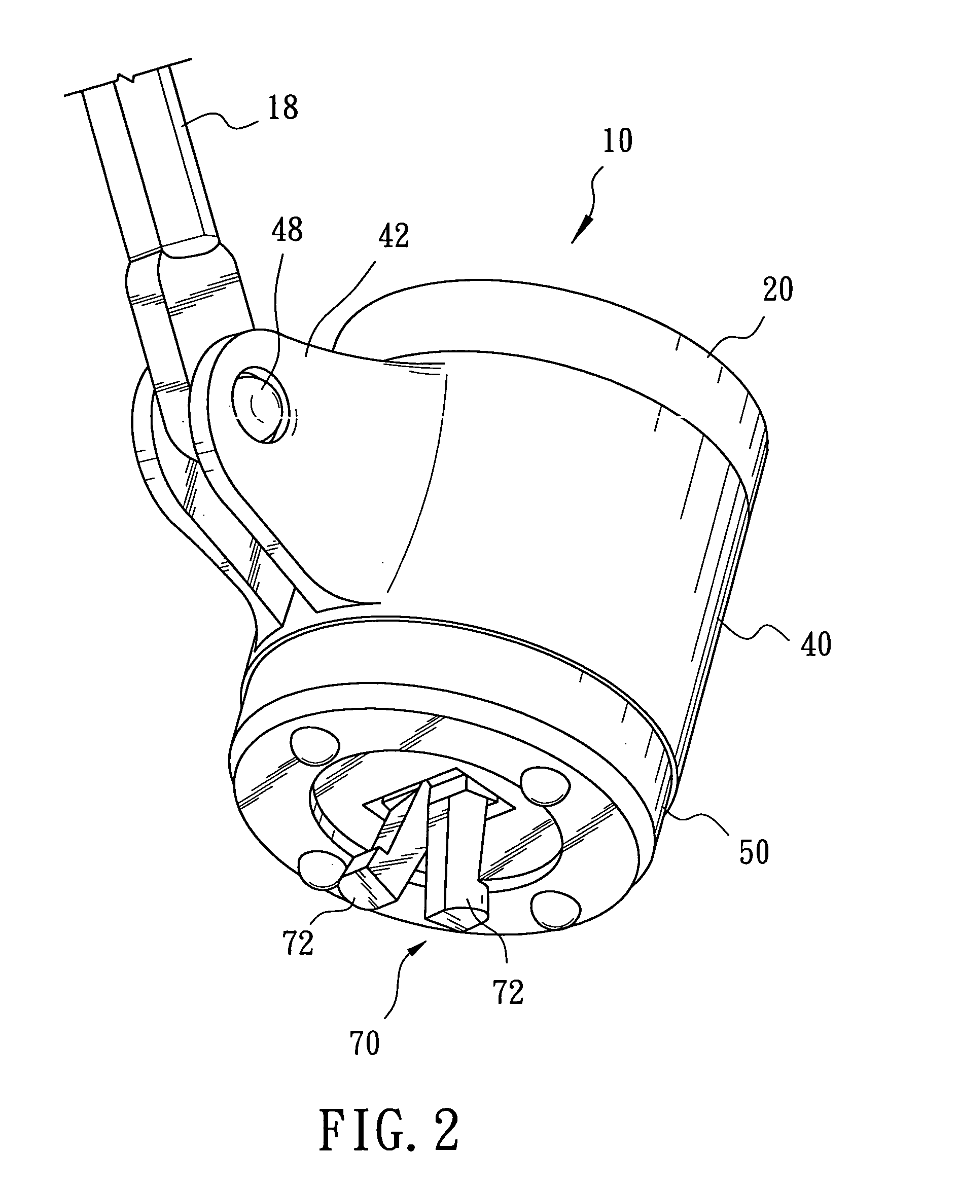
[0020]Referring to FIGS. 2-5, the computer security lock 10 includes a substantially cylindrical main housing 20, a cable holder 40, an end cap 50, a key-operated cylindrical lock 60, and a latch mechanism 70. The main housing 20 is generally cylindrical and has opposite first and second ends 22, 24. The second end 24 is a closed end having a slot 26 defined therein....


PUM


Abstract

A computer security lock includes a main housing, a key-operated lock having a lock housing disposed in the main housing and having a lock bar extending movably through the lock housing, and a pair of scissors-type levers. Each lever has opposite proximal and distal end portions, and a medial part between the proximal and distal end portions. The distal end portion has a hook extending outwardly of the main housing to engage a slot in a computer housing. The medial parts of the levers are pivoted to the main housing at a common pivot point. The proximal end portions of the levers are biased to place the hooks in an unlatching position in which the hooks overlap. A cam is moved by the lock bar to extend toward and between the proximal end protions so that the hooks move away from each other. A cable holder extends around the main housing, and a security cable is connected pivotally to the cable holder.

Description

CROSS-REFERENCE TO RELATED APPLICATION[0001]This application claims priority from Provisional Application No. 60 / 760,391 filed on Jan. 20, 2006.BACKGROUND OF THE INVENTION[0002]1. Field of the Invention[0003]The present invention relates to a computer security lock that can be fixed to a computer, more particularly to a combined computer security lock and security cable incorporating a latch mechanism that has a pair of scissors-type levers respectively provided with hooks to engage a slot provided in a computer housing.[0004]2. Description of the Related Art[0005]With the development of improved multimedia storage and display and the development of wireless networking, the so-called notebook or laptop computer has become increasingly popular. However, the portability of the notebook computer gives rise to concerns that the notebook computer is a tempting target for thieves. In order to deter thieves, a security cable may be attached to the computer. The security cable has a loop at...

Claims


Application Information

Patent Timeline
Patent Type & Authority Patents(United States)
IPC IPC(8): E05B69/00
CPCE05B73/0082E05B73/0005Y10T70/40Y10T70/409Y10T70/483Y10T70/5009
Inventor LU, FRANCISCO
Owner LU WEI HSIANG
Learn More