
Variable valve actuator

a valve actuator and variable technology, applied in the field of actuators, can solve the problems of limited ability to deal with high and/or variable cylinder air pressure, high electrical power demand, and inability or difficulty to control lift, etc., and achieve the effect of shortening the lift of the valve, efficient low load operation, and small lifting

Inactive Publication Date: 2007-12-04
LGD TECH LLC
View PDF14 Cites 6 Cited by
  • Summary
  • Abstract
  • Description
  • Claims
  • Application Information

AI Technical Summary

Benefits of technology

[0016]At either open or closed position, the engine valve is unlatched or released by toggling an actuation switch valve so that the pressure levels in the first and second fluid spaces are reversed, instead of being equalized as in the prior art, and thus the differential pressure force on the piston is also reversed, instead of just being reduced to almost zero like in prior art. Before the switch, the differential pressure force on the actuation piston is in opposite to and greater than the spring returning force to latch the engine valve. After the switch, the differential pressure force keeps substantially the same magnitude and reverses its direction to help the spring returning force drive the engine valve to the other position, feeding additional hydraulic energy into the system.
[0018]According to the invention, the engine valve is initialized to the closed position by supply high pressure fluid to a chamber under a start piston fixed on the first piston rod. Alternatively, the engine valve is initialized to the open position by supply high pressure fluid into a chamber directly above the first piston rod. In yet another alternative embodiment, a start shaft assembly is used to selectively close and disable the bypass means so that the actuation piston and cylinder system can be directly used for its own startup. Also, by blocking the bypass means with this start shaft assembly, the actuator can be operated selectively with a much smaller lift.
[0019]The present invention provides significant advantages over other actuators and valve control systems, and methods for controlling actuators and / or engine valves. For example, by adding a substantial hydraulic force to coincide with the spring returning force at the beginning of each stroke, the system can help overcome the engine-cylinder air pressure and compensate for frictional losses. The ability of an alternative preferred embodiment to provide a shorter valve lift is very beneficial to achieve efficient low load operation in certain engine control strategies. The present invention is able to incorporate lash adjustment into all alternative preferred embodiments. It is also possible to trigger and complete one engine valve stroke by just one, instead of two, switch actions of the actuation switch valve.

Problems solved by technology

Problems with an electromechanical camless system include difficulty associated with soft-landing, high electrical power demand, inability or difficulty to control lift, and limited ability to deal with high and / or varying cylinder air pressure.
An electrohydraulic camless system can generally overcome such problems, but it does have its own problems such as performance at high engine speeds and design or control complexity, resulting from the conflict between the response time and flow capability.
These requirements have stretched the limit of conventional electrohydraulic technologies.
As discussed above, there have been difficulties associated with electromechanical or electromagnetic latch-release devices.
The system just described has several potential problems.
The 2-way boost valve is driven by differential pressure inside the two cylinder chambers, or stroke spaces as the inventers refer as, and there is potentially too much time delay and hydraulic transient waves between the boost valve and cylinder chambers.
During a closing stroke, there is no effective means to add additional hydraulic energy until near the very end of the stroke, which may be a problem if there are too much frictional losses.
One drawback of the hydraulic spring is its rapid pressure drop once the engine valve movement starts.
Another common issue is the length of the actuator with the two compression springs separated by a hydraulic spring.
When the springs are aligned on the same axis, as disclosed in U.S. Pat. No. 5,809,950, the total height may be excessive.
In the remaining patents of this family, the springs are not aligned on a straight axis, but are instead bent at the hydraulic spring, and the fluid inertia, frictional losses, and transient hydraulic waves and delays may become serious problems.
Another common problem is that the closing stroke is driven by the spring pendulum energy only, and an existence of substantial frictional losses may pose a serious threat to the normal operation.
Much like the DaimlerChrysler disclosures, it has no effective means to add hydraulic energy at the beginning of a stroke to compensate for the engine cylinder air force and friction losses.
It is not capable of adjusting valve lift either.

Method used


Image

  • Variable valve actuator
  • Variable valve actuator
  • Variable valve actuator

Examples


Embodiment Construction

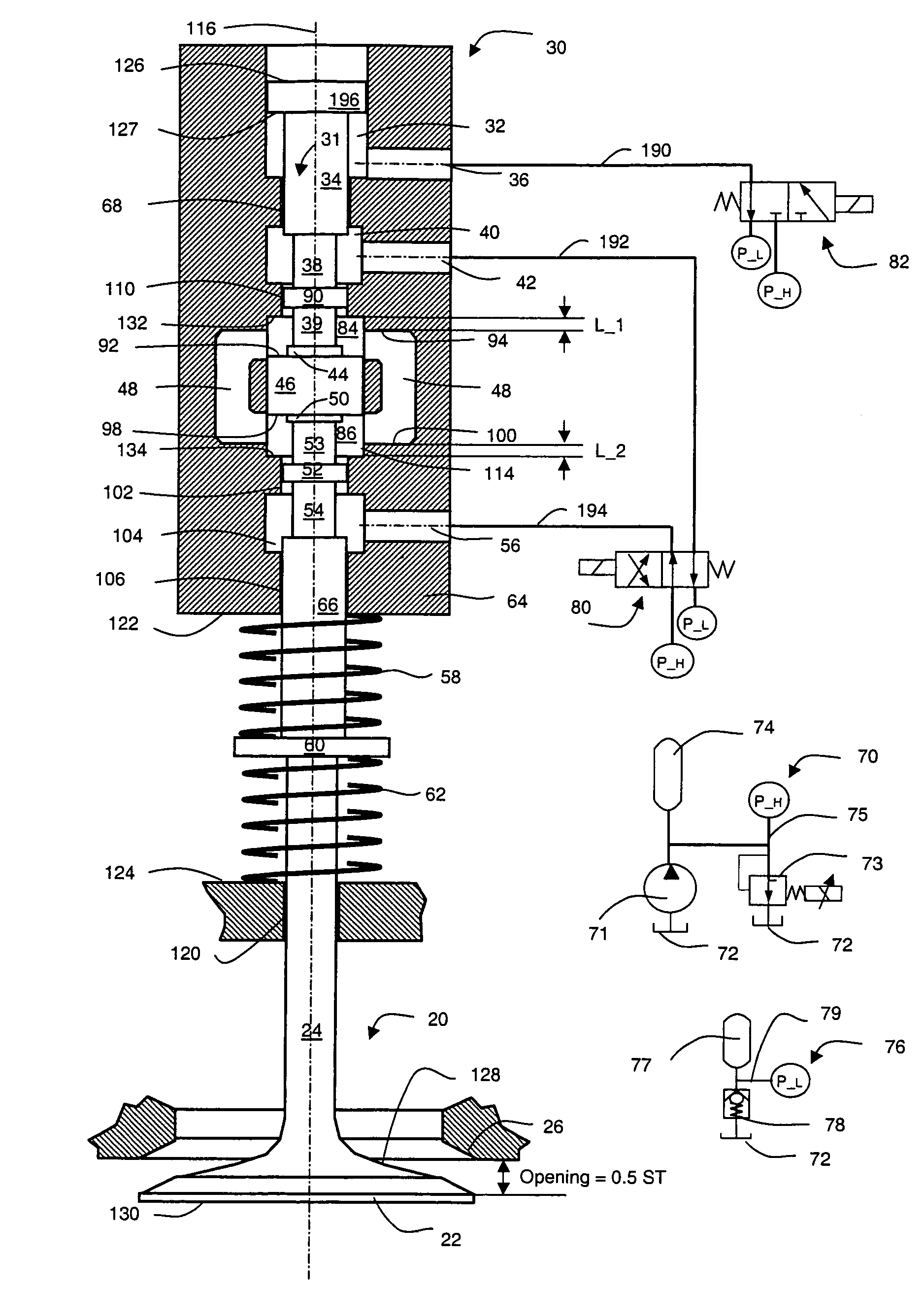
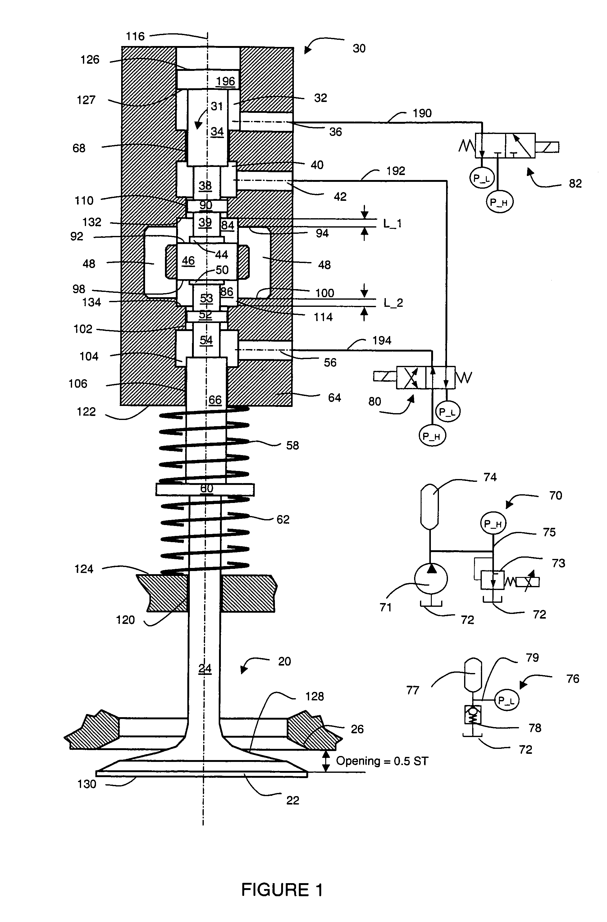
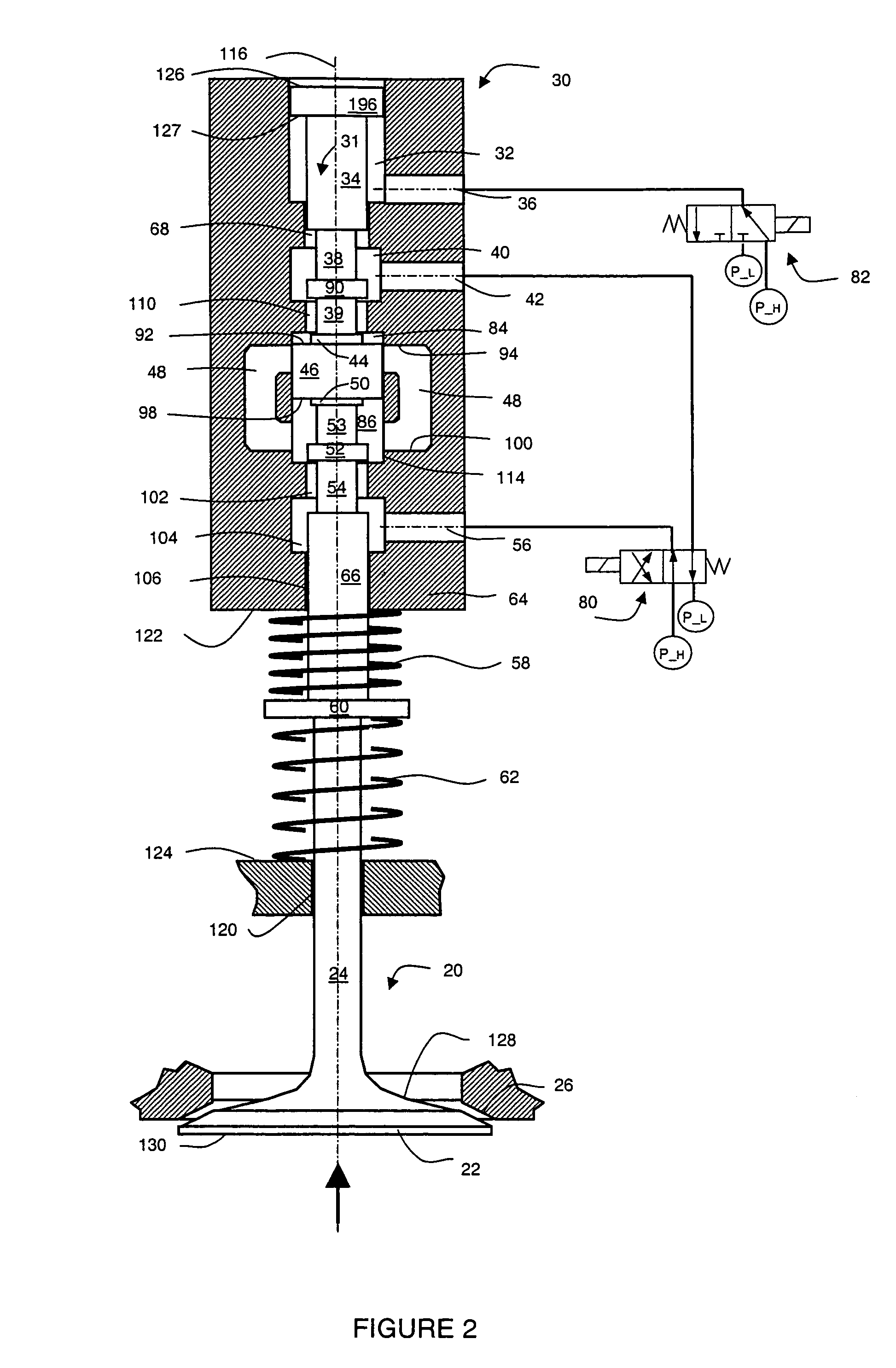
[0034]Referring now to FIG. 1, a preferred embodiment of the invention provides an engine valve control system using two pistons, one or more bypass passages, and a pair of spring means. The system comprises an engine valve 20, a hydraulic actuator 30, a high-pressure hydraulic source 70, a low-pressure hydraulic assembly 76, an actuation switch valve 80, and a start switch valve 82.

[0035]The high-pressure hydraulic source 70 includes a hydraulic pump 71, a high-pressure regulating valve 73, a high-pressure accumulator or reservoir 74, a high-pressure supply line 75, and a hydraulic tank 72. The high-pressure hydraulic source 70 provides necessary hydraulic flow at a high-pressure P_H. The hydraulic pump 71 circulates hydraulic fluid from the hydraulic tank 72 to the rest of the system through the high-pressure supply line 75. The high-pressure P_H is regulated through the high-pressure regulating valve 73. The high-pressure accumulator 74 helps smooth out pressure and flow fluctuat...


PUM


Abstract

Actuators, and corresponding methods and systems for controlling such actuators, provide independent lift and timing control with minimum energy consumption. In an exemplary embodiment, an actuation cylinder in a housing defines a longitudinal axis and having first and second ends in first and second directions. An actuation piston in the cylinder, with first and second surfaces, is moveable along the longitudinal axis. First and second actuation springs bias the actuation piston in the first and second directions, respectively. A first fluid space is defined by the first end of the actuation cylinder and the first surface of the actuation piston, and a second fluid space is defined by the second end of the actuation cylinder and the second surface of the actuation piston. A fluid bypass short-circuits the first and second fluid spaces when the actuation piston is not substantially proximate to either the first or second end of the actuation cylinder. A first flow mechanism is provided in fluid communication between the first fluid space and a first port, and a second flow mechanism is provided in fluid communication between the second fluid space and a second port. The term “fluid” includes both liquids and gases, and the actuator may be coupled to a stem to form a variable valve actuator in an internal combustion engine, for example.

Description

FIELD OF THE INVENTION[0001]This invention relates generally to actuators and corresponding methods and systems for controlling such actuators, and in particular, to actuators providing independent lift and timing control with minimum energy consumption.BACKGROUND OF THE INVENTION[0002]Various systems can be used to actively control the timing and lift of engine valves to achieve improvements in engine performance, fuel economy, emissions, and other characteristics. Depending on the means of the control or the actuator, these systems can be classified as mechanical, electrohydraulic, and electromechanical (sometimes called electromagnetic). Depending on the extent of the control, they can be classified as variable valve-lift and timing, variable valve-timing, and variable valve-lift. They can also be classified as cam-based or indirect acting and camless or direct acting.[0003]In the case of a cam-based system, the traditional engine cam system is kept and modified somewhat to indir...

Claims


Application Information

Patent Timeline
Patent Type & Authority Patents(United States)
IPC IPC(8): F01L9/02F01L9/10
CPCF01L9/02F01L13/00F01L2001/34446F01L9/10
Inventor LOU, ZHENG
Owner LGD TECH LLC
Learn More