Hydraulic railhead track jack and use method thereof

A technology of rail lifter and rail head, applied in the field of hydraulic rail head lifter, can solve the problems of waste of time cost and labor cost, unable to place the rail lifter base, unable to use the rail lifter, etc., so as to reduce maintenance time, Significant management benefits and high operational efficiency

Pending Publication Date: 2018-09-28
上海瑞纽机械股份有限公司
View PDF0 Cites 3 Cited by
  • Summary
  • Abstract
  • Description
  • Claims
  • Application Information

AI Technical Summary

Problems solved by technology

[0004] However, there is a common problem in the lifters of the above two typical structures, which requires a large working space when in use.
Because the operating force application points of the two kinds of track lifters are located on the rail bottom plane, this requires a large space between the rail and the ground to install the force application mechanism. Although the force rod can enter the small space at the bottom of the rail under special circumstances, the base of the track lifter cannot be placed, making it unusable
For the lifter that completely depends on jacking up, the small space will cause the lifter to be completely unusable
[0005] For the track lifting operation in the wide sleeper slab area, there are a large number of integral ballast bed sections where the distance between the rail bottom and the ballast bed is ≤25mm. There is a phenomenon of deflection during the track, and there is currently no corresponding professional small-scale track lifter at home and abroad. It is mainly used in combination with conventional track lifters, track lifters and external assistance, but the operation is difficult, the operation is inconvenient, and the efficiency is high. At the same time, the quality of work is not good, and the waste of time and labor costs can be seen in general

Method used


Image

  • Hydraulic railhead track jack and use method thereof
  • Hydraulic railhead track jack and use method thereof
  • Hydraulic railhead track jack and use method thereof

Examples


Embodiment Construction

[0036] The technical solutions of the present invention will be further described below in conjunction with the accompanying drawings and embodiments.

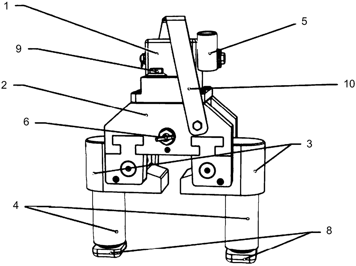
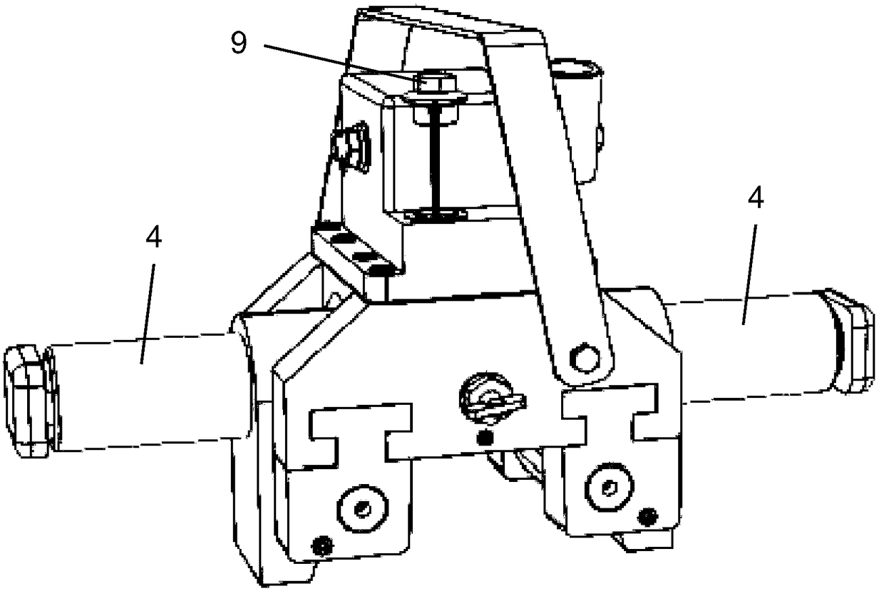
[0037] Please combine Figure 1 to Figure 2 As shown, a hydraulic rail head lifter provided by the present invention includes: a fuel tank 1 and a base 2, the fuel tank 1 is arranged on the top of the base 2, a pressing handle 5 is connected to the fuel tank 1, and the base 2 is also provided with Manual oil return valve 6, the bottom of the base 2 is provided with a channel structure. The lifting structure is designed with symmetrical double oil cylinders. This design is a key point to solve the lifting operation in small space in the wide sleeper area. On the one hand, it reduces the volume and weight of the whole machine, and on the other hand, it eliminates the unbalanced load of the existing lifting device.

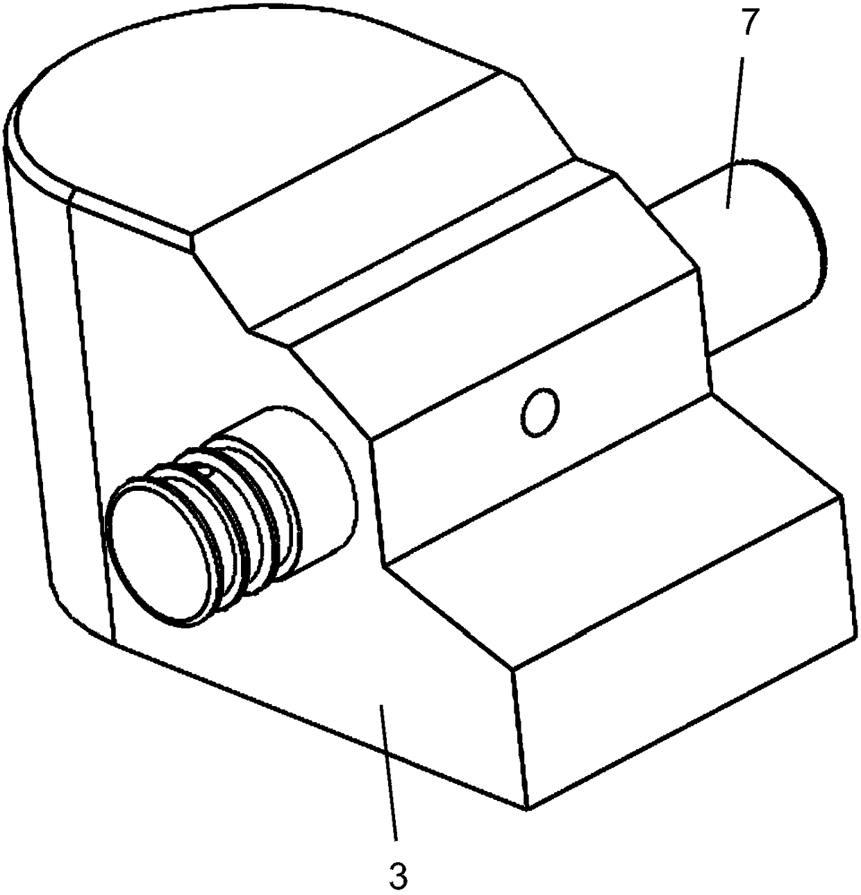
[0038] Preferably, the track lifting structure includes: a pair of track lifting hooks 3 that are symmetrically a...


PUM


Abstract

The invention discloses a hydraulic railhead track jack and a use method thereof. The hydraulic railhead track jack comprises an oil tank and a base; the oil tank is arranged at the top of the base; alifting handle is connected to the oil tank; a manual oil return valve is also arranged on the base; a track lifting structure is arranged at the bottom of the base; the track lifting structure comprises a pair of track lifting hooks symmetrically arranged; hook heads of the two track lifting hooks are also oppositely arranged; rotating shafts are arranged on the track lifting hooks; the interiors of the rotating shafts are in communication with the oil tank; the track lifting hooks are connected to the bottom of the base through rotating shafts so that the track lifting hooks turn over to the external sides for 90 degrees to rotate around the rotating shafts; a hydraulic oil cylinder is connected to each track lifting hook; the two hydraulic oil cylinders are also symmetrically arranged;and rotatable feet are connected to piston ends of the hydraulic oil cylinders. The hydraulic railhead track jack can be applicable to but not limited to the track lifting operations of broad-gauge sleeper slabs under a situation of a small space.

Description

technical field [0001] The invention relates to a track lifter, more specifically, to a hydraulic rail head track lifter and its usage method. Background technique [0002] There are still a considerable number of wide sleeper sections in the existing high-speed railway station lines. For the maintenance and maintenance of these wide sleeper sections, the sand pad operation and the addition and removal of rubber pads are the ideal methods. Difficulties, lack of corresponding suitable equipment, the main reason is that the distance between the rail bottom and the ballast bed is far less than or equal to 25mm, there is no space at both ends of the sleeper board, or it is a cement floor, and the existing equipment lacks force points. [0003] Existing track lifter has a lot of different models, mainly contains hydraulic lifter and rack track lifter. The hydraulic track lifter is suitable for the track on the main line of the rail, and the track lifting operation of the turnout...

Claims


Application Information

Patent Timeline
IPC IPC(8): E01B29/04
CPCE01B29/04
Inventor 杨奎山何平平吴祖鹏黄智郑芳杰陈卫
Owner 上海瑞纽机械股份有限公司
Why Eureka
Try Eureka