Electromechanical variable valve actuator with a spring controller

a technology of electric motor and actuator, which is applied in the direction of valve arrangement, non-mechanical valve, machines/engines, etc., can solve the problems of increasing the electrical energy consumption of the vehicle, and affecting the operation of the vehicle. , to achieve the effect of small lifting, good start-up point and stable operation

Inactive Publication Date: 2009-09-22
LGD TECH LLC
View PDF3 Cites 3 Cited by
  • Summary
  • Abstract
  • Description
  • Claims
  • Application Information

AI Technical Summary

Benefits of technology

[0010]In another embodiment, the spring controller allows the engine valve to operate with a small lift when the control fluid pressure is below a certain level or threshold. In still another embodiment, the spring controller includes a damping mechanism, without too much more complexity, to stabilize its operation.
[0011]The present invention provides significant advantages over the prevailing EMVVA actuators and their control. For example, it can effectively close the engine valve at power-off to meet certain vehicle regulations. The closed engine valve is also a good start-up point for the next power-on procedure or initialization. The invention also provides means to efficiently and effectively operate engine valves with a small lift. The present invention thus provides, with one mechanism, at least three significant functions: a closed engine valve at power-off, easy start-up, and partial or variable stroke. The present invention also provides partial stroke operation stability without too much more complexity.

Problems solved by technology

The prevailing EMVVA design does have several problems or potential problems.
Also, to initialize an EMVVA actuator at the start of power-on, great effort and a large amount electrical current are spent to pull the armature from the middle point to either of the two electromagnets because of the nonlinear nature of the electromagnetic force.
Some prevailing EMVVA actuators may perform short-lift actuation, but at great expense of electrical energy sustaining a large electromagnetic force through a substantial air gap to counter the spring centering force.
This additional electrical energy further stretches the limit of a vehicle electrical system, especially during low load and idle operations when the vehicle alternator or electrical generator is the least efficient.
However, it fails to provide a solution to meet the need to keep the engine valve closed at power-off , and it also entails an additional hydraulically-operated-and-controlled locking mechanism, which incurs added complexity and reliability concern, to stabilize the adjusting device for partial stoke operations.

Method used


Image

  • Electromechanical variable valve actuator with a spring controller
  • Electromechanical variable valve actuator with a spring controller
  • Electromechanical variable valve actuator with a spring controller

Examples


Embodiment Construction

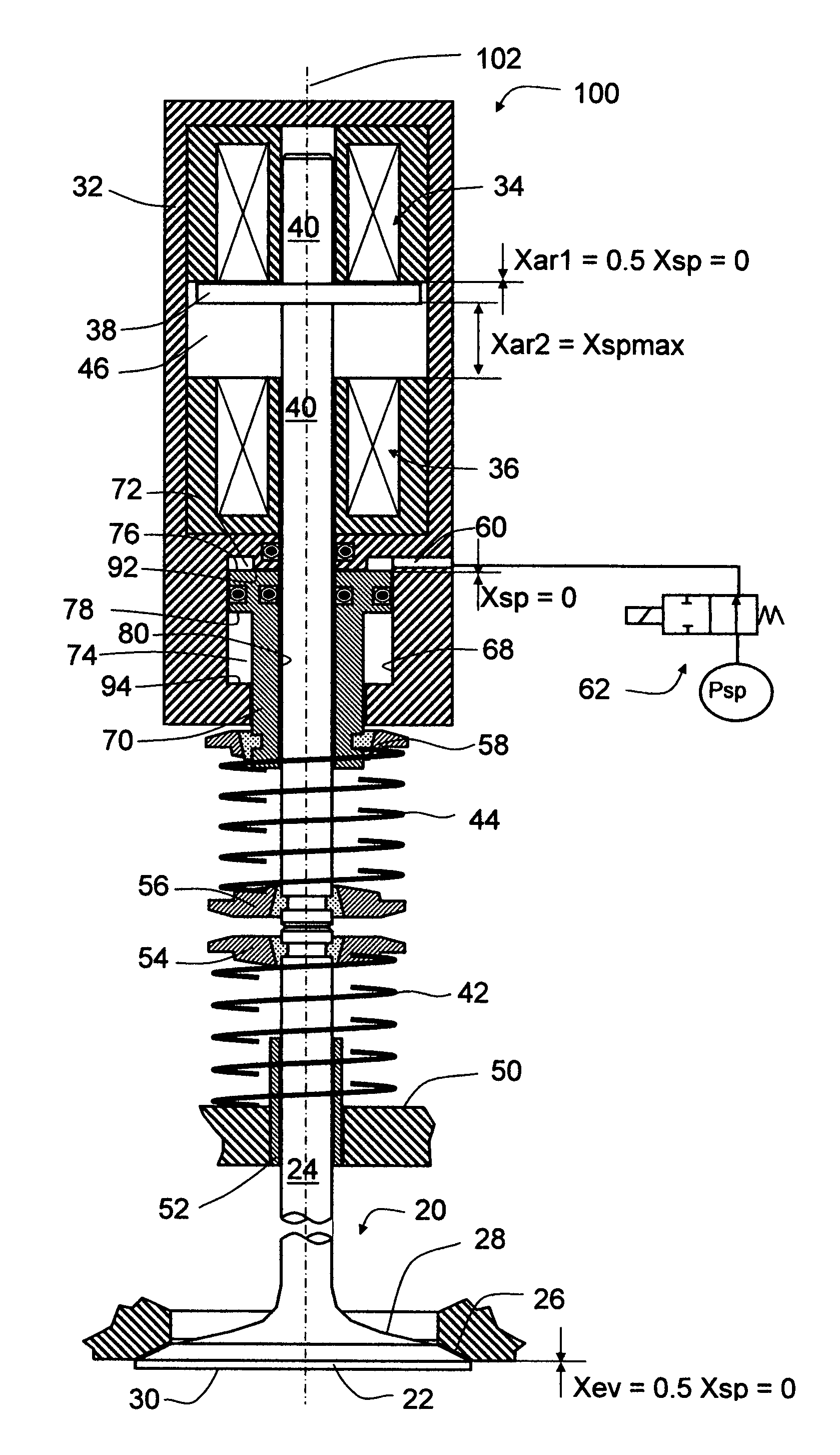
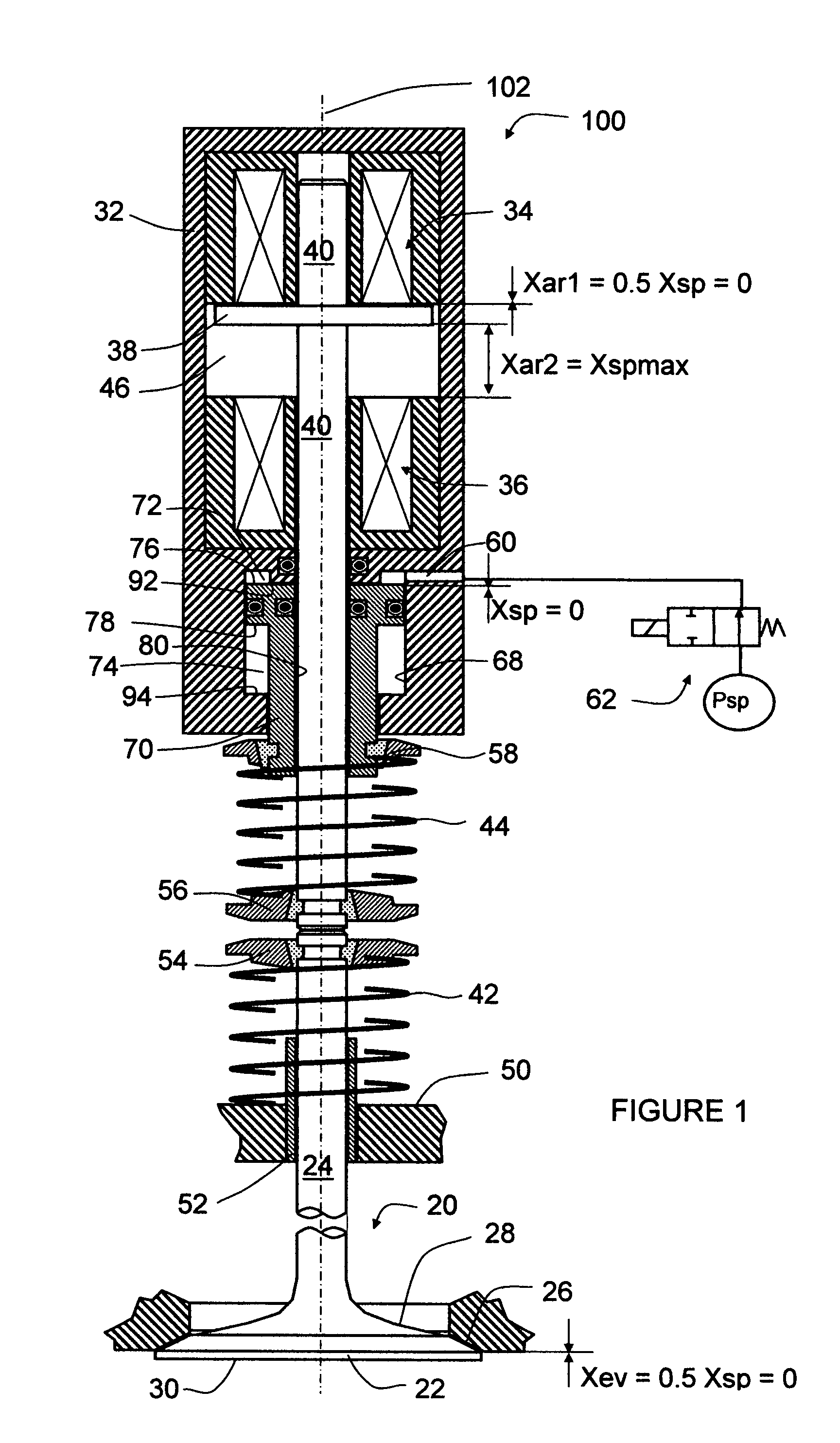
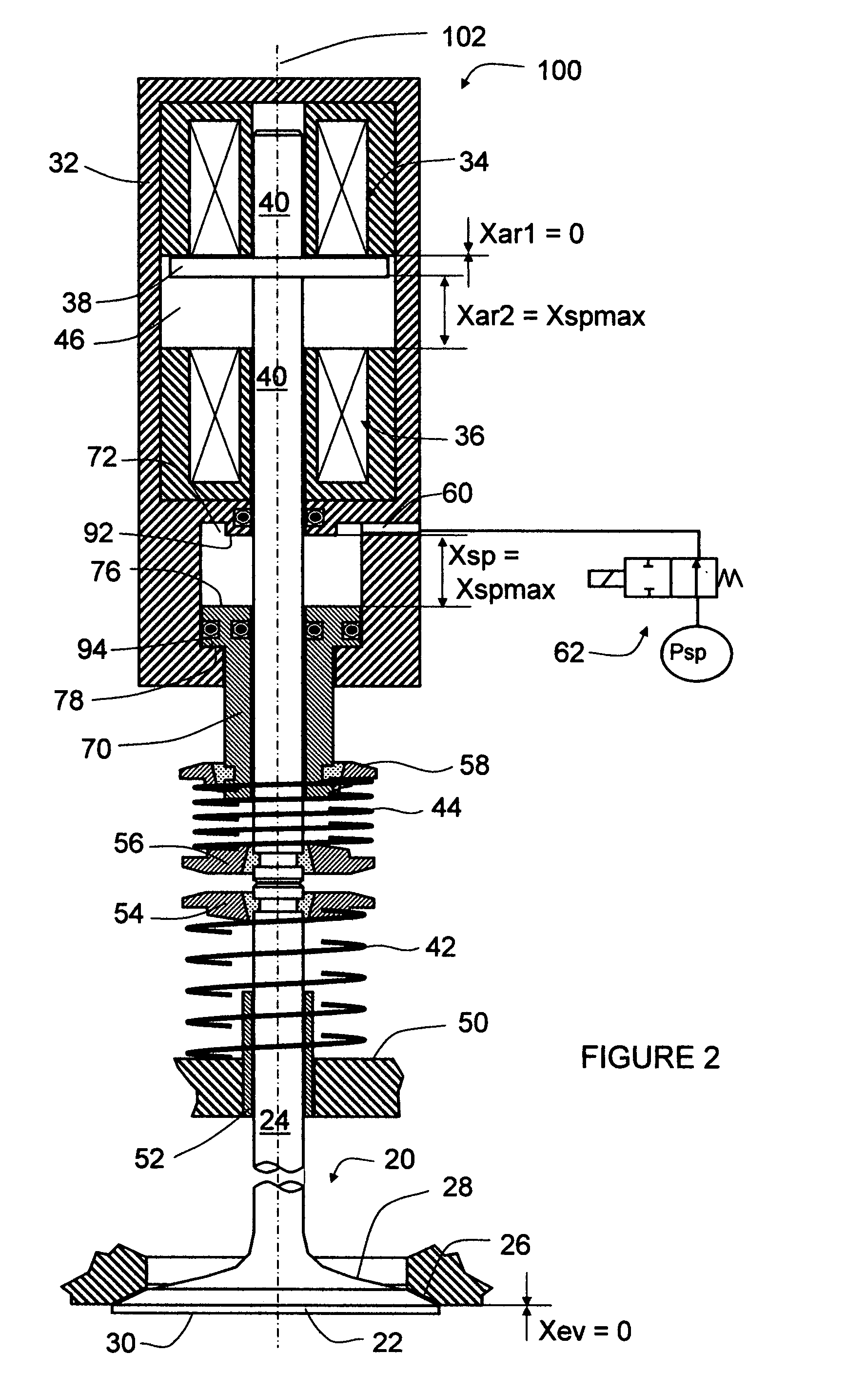
[0022]Referring now to FIG. 1, a preferred embodiment of the invention provides an engine valve control actuator 100. The actuator 100 includes a housing 32. Rigidly disposed within the housing 32, along the longitudinal axis 102 and from a first to a second direction (from the top to the bottom in the drawing), are a first electromagnet 34, an armature chamber 46, a second electromagnet 36, and a spring-controller cylinder 68. The first and second electromagnets 34 and 36 further include their electrical windings and lamination stacks. An armature 38 is disposed inside the armature chamber 46 and between the first and second electromagnets 34 and 36 and is rigidly connected to an armature rod 40. The armature rod 40 is slideably disposed through the first and second electromagnets 34 and 36, the housing 32, and a spring controller 70. The spring controller 70 is slideably disposed within the spring-controller cylinder 68 and through the second-direction end of the housing 32. The a...


PUM


Abstract

Actuators, and corresponding methods and systems for controlling such actuators, provide independent lift and timing control with minimum energy consumption. In an exemplary embodiment, an electromechanical actuator comprises a housing, first and second electromagnets rigidly disposed in the housing and separated from each other by an armature chamber, an armature disposed in the armature chamber and movable between the first and second electromagnets, an armature rod rigidly connected with the armature and operably connected with a load, at least one first actuation spring biasing the armature in a first direction, at least one second actuation spring biasing the armature in a second direction, and one fluid-operated spring controller capable of controlling the position of the first-direction end of the at least one second actuation spring. The spring controller allows the actuation springs at their least compressed state and the engine valve closed when engine power is off. The spring controller may also be adjusted, with a low or moderate control fluid pressure, to allow the engine valve to operate with a partial lift.

Description

REFERENCE TO RELATED APPLICATION[0001]This application claims priority to Provisional U.S. Patent Application No. 60 / 765,012, file on Feb. 3, 2006, the entire content of which are incorporated herein by reference.FIELD OF THE INVENTION[0002]This invention relates generally to actuators and corresponding methods and systems for controlling such actuators, and in particular, to actuators providing independent lift and timing control with minimum energy consumption.BACKGROUND OF THE INVENTION[0003]Variable valve actuation (VVA) systems are used to actively control the timing and lift of engine valves to achieve improvements in engine performance, fuel economy, emissions, and other characteristics. Depending on the means of the control or the actuator, VVA systems are classified as mechanical, electrohydraulic, and electromechanical (sometimes called electromagnetic). Depending on the extent of the control, they are classified as variable valve-lift and timing, variable valve-timing, an...

Claims


Application Information

Patent Timeline
Patent Type & Authority Patents(United States)
IPC IPC(8): F01L9/04F01L9/20F01L9/10
CPCF01L9/02F01L9/04F01L2009/0426F01L2009/2126F01L9/10F01L9/20
Inventor LOU, ZHENG
Owner LGD TECH LLC
Why Eureka
Try Eureka