Sprinkler having valve module with reciprocating valve seat

Active Publication Date: 2007-12-04
HUNTER INDUSTRIES
View PDF8 Cites 55 Cited by
  • Summary
  • Abstract
  • Description
  • Claims
  • Application Information

AI Technical Summary

Problems solved by technology

When the valve is in its CLOSED or turbine state such high water pressures ...

Method used


Image

  • Sprinkler having valve module with reciprocating valve seat
  • Sprinkler having valve module with reciprocating valve seat
  • Sprinkler having valve module with reciprocating valve seat

Examples


Embodiment Construction

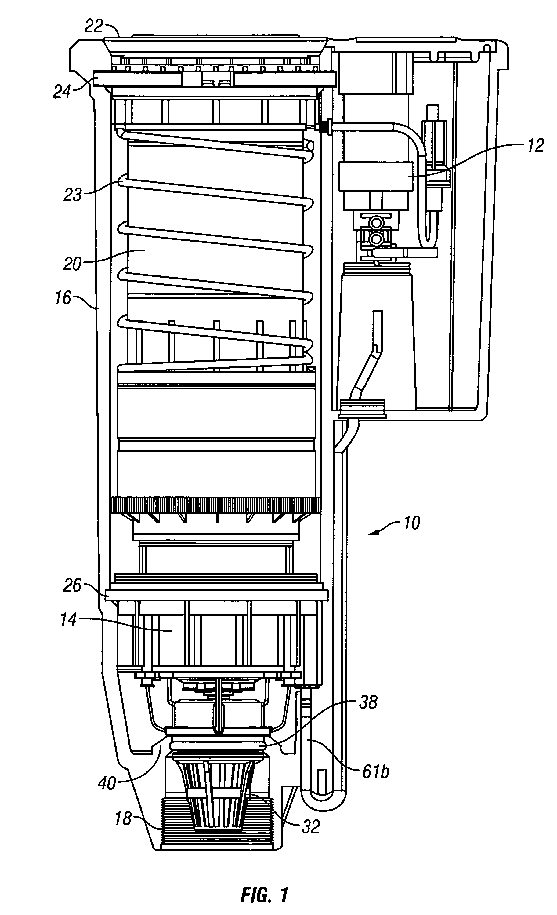
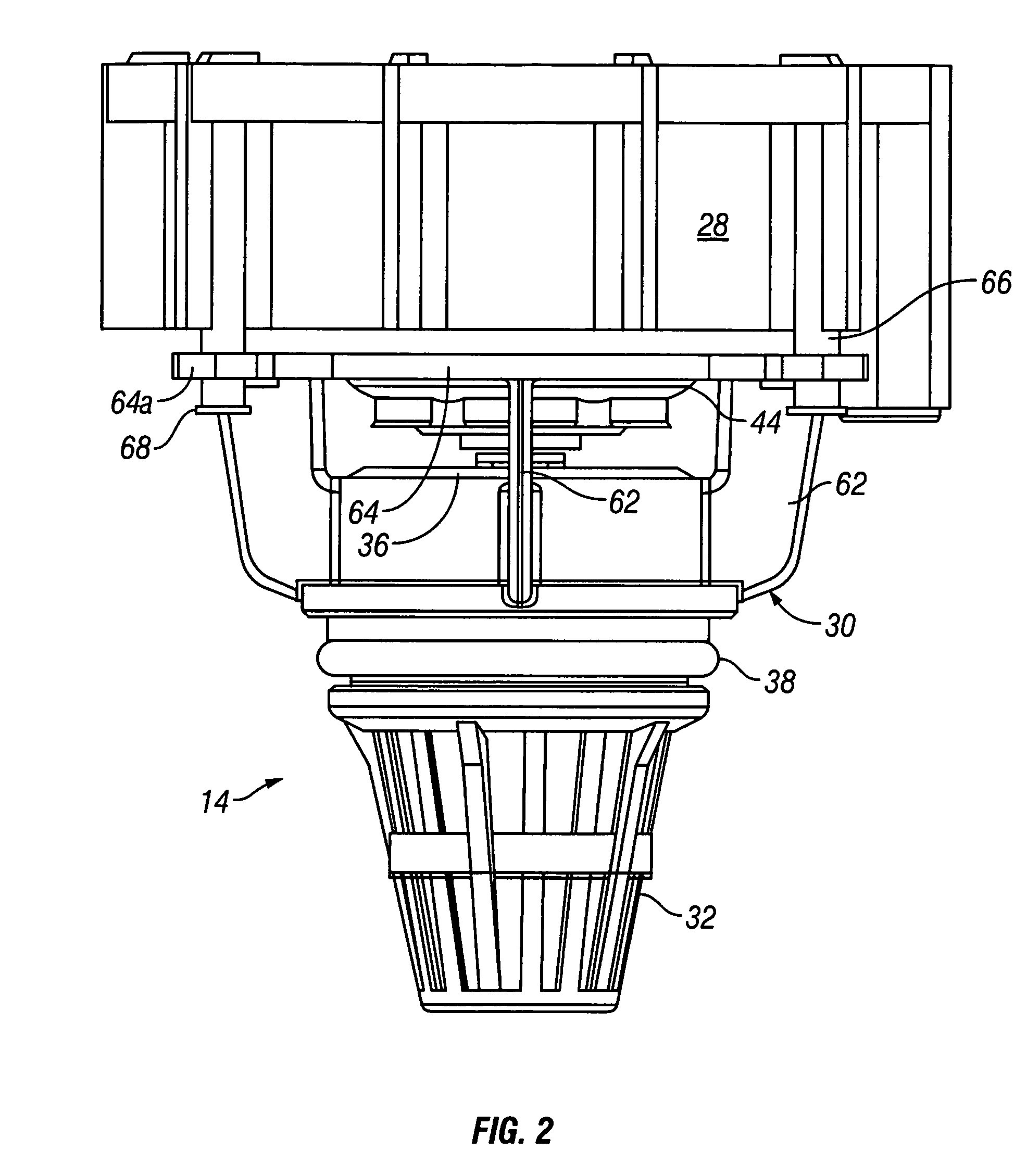
[0014]The entire disclosure of U.S. Pat. No. 6,491,235 granted Dec. 10, 2002 to Scott et al. is hereby incorporated by reference. Referring to FIG. 1, a valve-in-head rotor type sprinkler 10 includes a valve actuator component assembly 12 and a top serviceable diaphragm valve module 14. The valve module 14 is mounted in the lower end of a generally cylindrical outer case 16 having a female threaded inlet 18. A tubular riser 20 is vertically reciprocable within the outer case 16 when the valve module 12 is opened and closed. A cylindrical nozzle head or turret 22 is rotatably mounted at the upper end of the riser 20. The riser 20 is held in its retracted position by a coil spring 23 held in place by an upper snap ring 24. A turbine (or other impeller such as a ball drive), gear reduction, and reversing mechanism (not visible) are mounted in the riser 20 and rotate the nozzle turret 22 through an adjustable arc, as well known in the art. A lower snap ring 26 releasably holds the valve...


PUM


Abstract

A sprinkler includes an outer case and a riser mounted for reciprocation within the case. The riser supports a nozzle, an impeller, and a drive linkage connecting the nozzle and the impeller. A diaphragm valve is mounted in outer case beneath the riser and includes a valve member vertically reciprocable within a valve support housing to engage and disengage a valve seat. The valve seat can reciprocate relative to the valve support housing to reduce mechanical loading.

Description

FIELD OF THE INVENTION[0001]The present invention relates to sprinklers used to irrigate lawns, gardens and landscaping, and more particularly, to so-called valve-in-head sprinklers that have built in valves for turning ON and OFF the application of water by the sprinkler.BACKGROUND[0002]Irrigation systems used in homes typically comprise a garage-mounted electronic controller that selectively turns a plurality of solenoid actuated valves ON and OFF in accordance with a pre-programmed watering schedule. The valves admit water to subterranean PVC pipes having several spray, rotor-type or drip-type sprinklers attached to the pipes at spaced intervals. The solenoid actuated valves are usually housed together in a plastic valve box buried near the electronic controller.[0003]In some environments, such as golf courses, so called “valve-in-head” sprinklers are preferred. They have a diaphragm valve built into the lower end thereof which is typically actuated by a solenoid mounted in the s...

Claims


Application Information

Patent Timeline
IPC IPC(8): B05B15/10B05B15/06B05B3/04F16K25/00F16K31/12
CPCB05B1/304B05B15/10B05B3/0418B05B15/74
Inventor DANNER, FRED M.SMITH, JEFF M.
Owner HUNTER INDUSTRIES
Why Eureka
Try Eureka