Intervertebral implant

a technology of intervertebral implants and implants, which is applied in the field of intervertebral implants, can solve the problems of impossible post-surgical assessment of the fusion of vertebrae, and achieve the effect of preventing the implant and high degree of primary stability

Inactive Publication Date: 2007-12-04
SYNTHES USA
View PDF21 Cites 163 Cited by
  • Summary
  • Abstract
  • Description
  • Claims
  • Application Information

AI Technical Summary

Benefits of technology

This patent describes an improved design for spinal implants that helps them stay securely positioned during surgery. It achieves this by creating a cavity at the back of the implant which fits snugly onto the vertebral body's end plate, providing initial stability. Additionally, there are slots within the implant that allow new bone growth to occur quickly and easily fill the space around the implant with natural tissue. These features make the implant more reliable and effective in treating degenerative disc disease or other spine-related conditions.

Problems solved by technology

This patent describes an improved design for spinal implants that can be observed through X-ray images after surgery. Previous versions were too visible on X-ray images, making it difficult to see how well they had fused with nearby tissue. The new version uses a special material called PEEK, which has a lower stiffness than other options like titanium. This allows for better bone growth around the implant.

Method used


Image

  • Intervertebral implant
  • Intervertebral implant
  • Intervertebral implant

Examples


Embodiment Construction

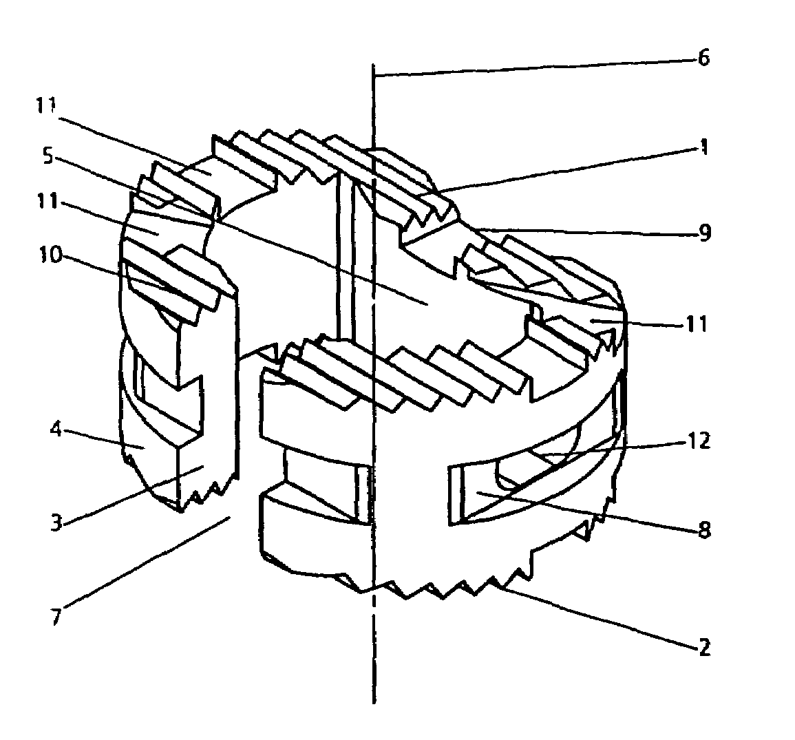
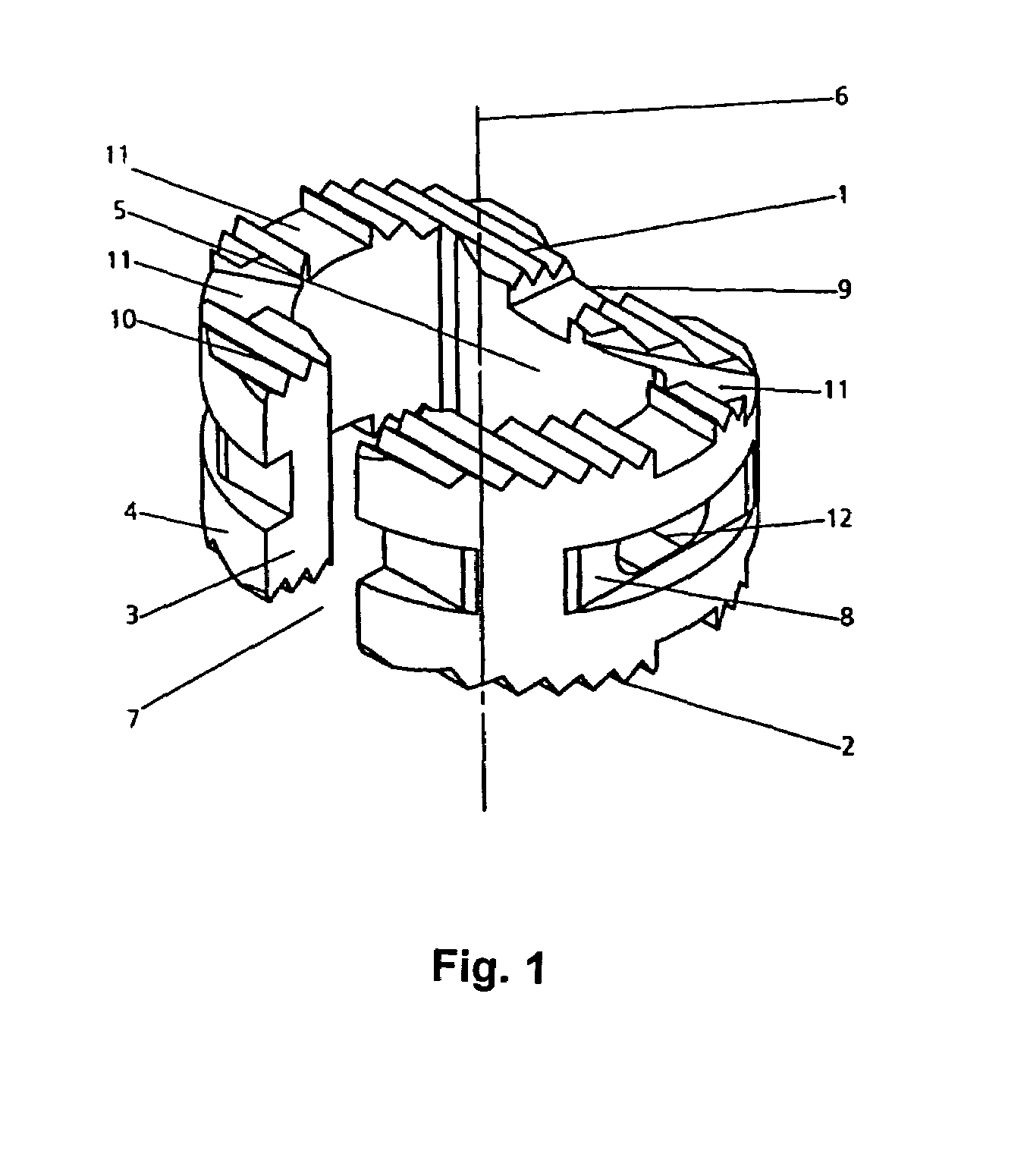
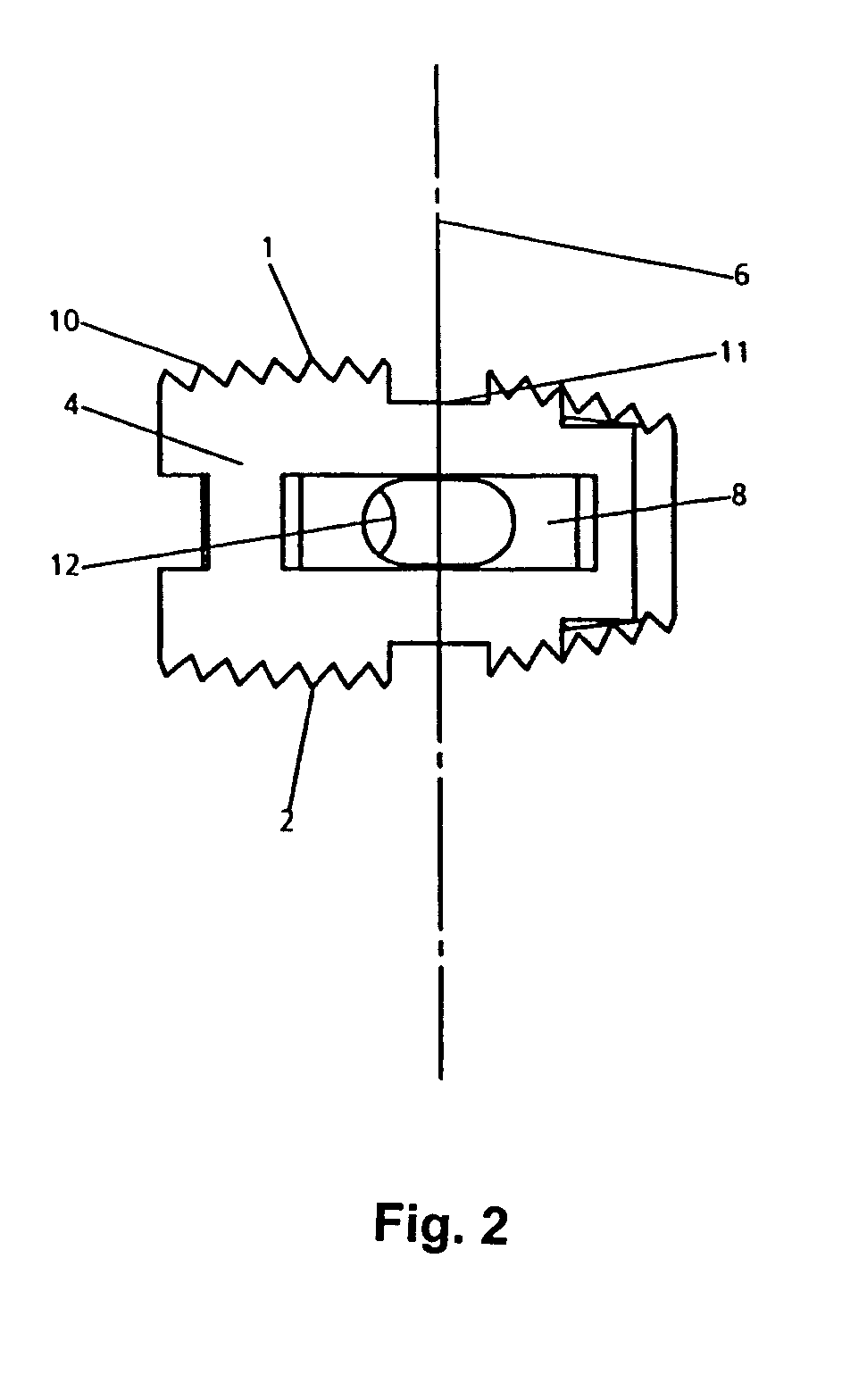
[0022]The intervertebral implant shown in FIGS. 1 and 2 is shaped in the form of a hollow cylinder. It has a first cover face 1, a second base face 2, a hollow cylinder wall 3 including an outer lateral area 4 and an inner lateral area 5, as well as a hollow cylinder central axis 6.

[0023]The implant is formed at least 95 percent by volume of a radiolucent material such as PEEK (group of polyaryletherketones). Such a material must have a modulus of elasticity of between 1 and 20 GPa. Preferably, the modulus of elasticity is between 3 and 5 GPa.

[0024]The intervertebral implant further includes three markers (not shown in the drawings) made of a radiopaque material (tantalum or titanium) which together form at most 5 percent by volume of said intervertebral implant. The total volume (100 percent) is to be understood as the volume occupied by the material of the intervertebral implant, excluding the hollow space enclosed by the implant.

[0025]The cover face 1 and the base face 2 of the i...


PUM


Abstract

An intervertebral implant is shaped in the form of a hollow cylinder and has a cover face, a base face, a hollow cylinder wall with an outer lateral area and an inner lateral area, as well as a hollow cylinder central axis. The implant is formed at least 95 percent by volume of a radiolucent material which has a modulus of elasticity of between 1 and 20 GPa. Postsurgical observation is permitted by means of X-rays, and at the same time the implant has a high degree of biocompatibility.

Description


Claims


Application Information

Patent Timeline
Owner SYNTHES USA
Why Eureka
Try Eureka