
Seating detection switch

a detection switch and seat technology, applied in the direction of diagnostic recording/measuring, contact mechanisms, pedestrian/occupant safety arrangements, etc., can solve the problem of the switch being damaged, and achieve the effect of preventing erroneous detection of the seat of a person and facilitating damag

Active Publication Date: 2007-12-04
THE FUJIKURA CABLE WORKS LTD +1
View PDF10 Cites 17 Cited by
  • Summary
  • Abstract
  • Description
  • Claims
  • Application Information

AI Technical Summary

Benefits of technology

The present invention provides a thin film-form seating detection switch that can detect whether or not a passenger is seated in a seat. The switch is made up of a film-form substrate, two conductors fixed to the substrate, and a film-form member that is insulated from the conductors. When a passenger sits down in a seat, the part of the substrate and the part of the member bend due to the weight of the passenger, causing the conductors to enter a condition of mutual conductivity. The switch is designed to prevent damage to the seat and to prevent incorrect detections. The invention also provides a seating detection switch that can detect whether or not a passenger is seated in a seat by using an AND circuit or an OR circuit.

Problems solved by technology

Thus, a problem arises in that it is troublesome to connect a connection terminal of an electrical wire (signal wire) provided by a wiring harness to each of the terminals.
As the conventional seating detection switch has a triple layer construction consisting of a film pairing with a spacer disposed therebetween, significant stress arises inside the seating detection switch in the parts subject to such curving and this may cause the switch to sustain damage.
Accordingly, a problem arises due to concern about the switch incorrectly detecting that a person has sat down in the seat if for example the edge of some luggage is positioned over a single contact pairing causing the contacts of that contact pairing to come into contact with each other, even though a person has not actually sat down in the seat.

Method used


Image

  • Seating detection switch
  • Seating detection switch
  • Seating detection switch

Examples


first embodiment

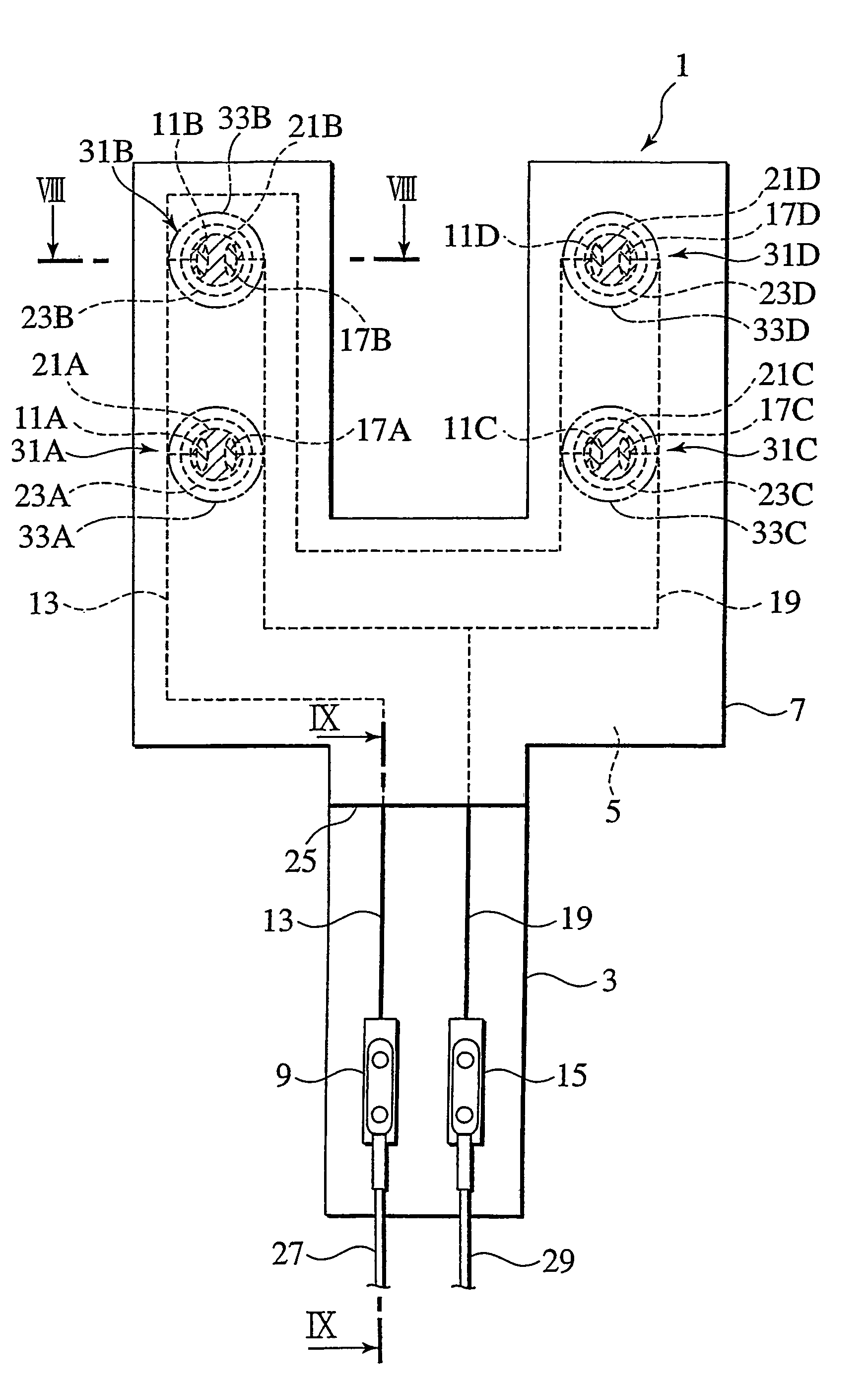
[0101]FIG. 7 schematically depicts a seating detection switch according to a first embodiment of the present invention. FIG. 8 is a cross-sectional view along the line VIII-VIII of FIG. 7. FIG. 9 is a cross-sectional view along the line IX-IX of FIG. 7. In FIG. 8 and FIG. 9 the seating detection switch 1 is drawn expanded in the direction of the thickness thereof (in FIG. 8 the vertical direction and in FIG. 9 a horizontal direction).

[0102]The seating detection switch 1 is arranged for example on the rear side of the covering of the seat of a car, and provides a thin, film-form seating detection switch capable of detecting whether or not a passenger is sitting in the seat.

[0103]The seating detection switch 1 comprises a film-form substrate 3 made of insulating material. A film-form member 7 made of insulating material is disposed over one of the surfaces of the film-form substrate 3, substantially parallel to and just apart from the film-form substrate 3, via a spacer 5 made of insu...

second embodiment

[0129]FIG. 13 is a schematic view of the seating detection switch 41 according to a second embodiment of the present invention.

[0130]This seating detection switch 41 differs from the seating detection switch 1 in the shape of the film-form substrate 43, the spacer 45 and the film-form member 47, and in respect of the provision of the nine switch portions 49A-49I. In all other respects this switch 43 is substantially the same as the switch 1.

[0131]That is to say, the film-form substrate 43, spacer 45 and film-form member 47 of the seating detection switch 41 branch into three on the side of the switch 41 opposite to that side where the terminals 9 and 15 are arranged, and three switch portions are arranged on each of these three branches. The switch portions 49A-49I form an OR circuit.

[0132]At the side of the film-form substrate 43 at which the terminals 9 and 15 are disposed, an extending part 51 is provided at which the spacer 45 and the film-form member 47 are removed.

[0133]The se...

third embodiment

[0166]FIG. 16 is a schematic view of a seating detection switch according to a third embodiment of the present invention.

[0167]The seating detection switch 61 in FIG. 16 differs from the seating detection switch 41 according to the second embodiment, in that parts 63A, 63B and 63C at which the spacer and film-form member are removed are further away from the terminals 9 and 15 and are each formed long over the central portion of the film-form substrate 63 that branches into three. In all other respects this seating detection switch 61 is generally the same as the seating detection switch 41.

[0168]The seating detection switch 61 installed on a car seat 73 will now be described.

[0169]FIG. 17 shows the seating detection switch 61 installed on a car seat 73.

[0170]The seat 73 comprises a seating part 75 and seat back 77. In the same manner as the seat 53, for comfortable seating of a passenger, in the seat 73 also the center area of the seating part 75 in the widthwise direction is divid...


PUM


Abstract

A thin, film-form seating switch able to detect whether an occupant sits on the seat or not, wherein, with a spacer (5) in-between, a film-form substrate (3) is disposed on one surface of the spacer and a film-form member (7) on the other surface, a first conductor (13) equipped with a first terminal (9) and a first electrode (11A) conductive with this and a second conductor (19) equipped with a second terminal (15) and a second electrode (17A) conductive with this are fixed to one surface of the film-form substrate, and a third conductor (21A) for letting the first electrode conduct with the second electrode when an occupant is seated is fixed to the film-form member (7). The above arrangement solves a conventional problem that it is troublesome to connect the connection terminals of wires or the like provided on a wiring harness or the like to respective terminals that are separately provided on a film-form substrate and a film-form member.

Description

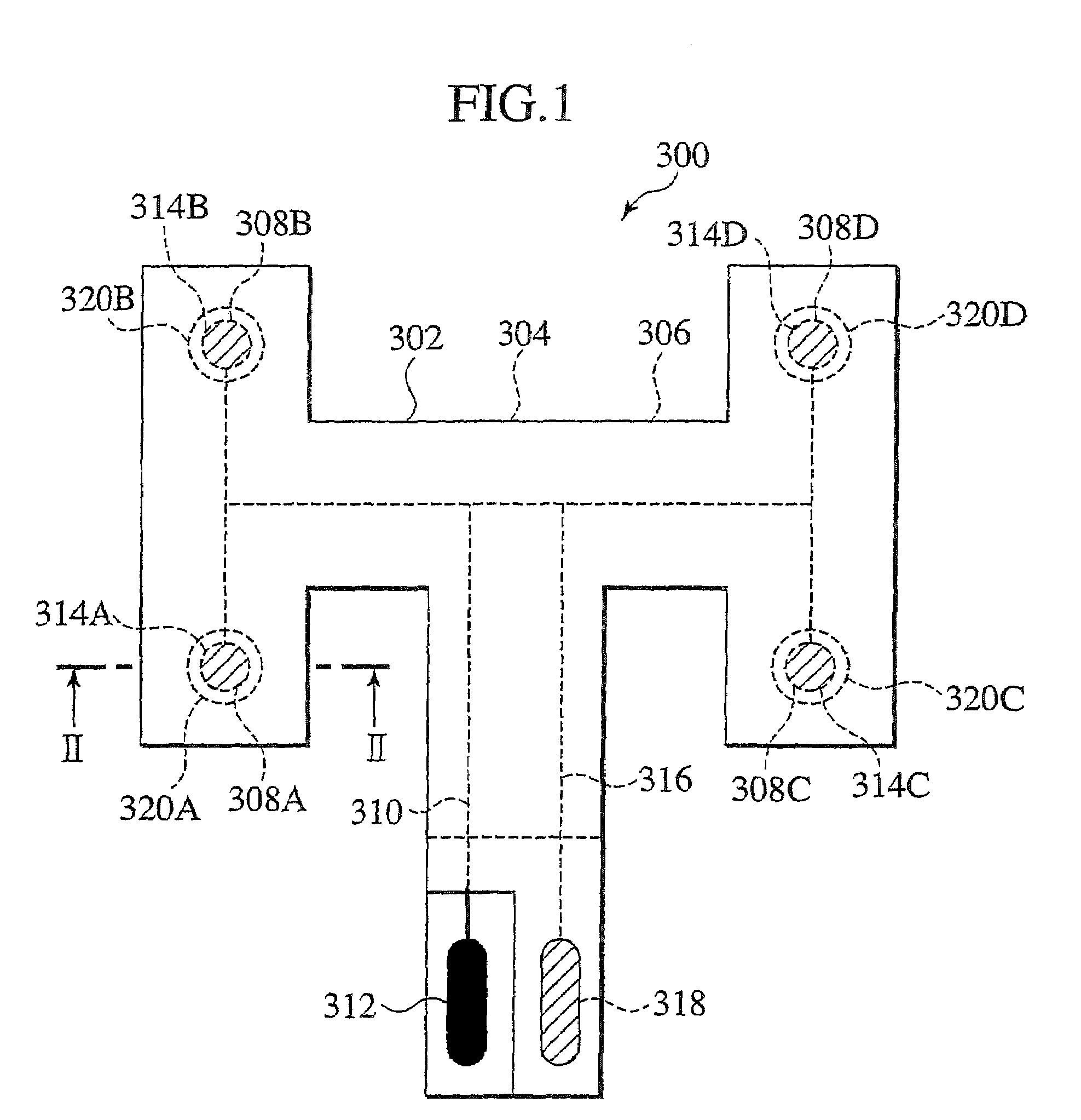
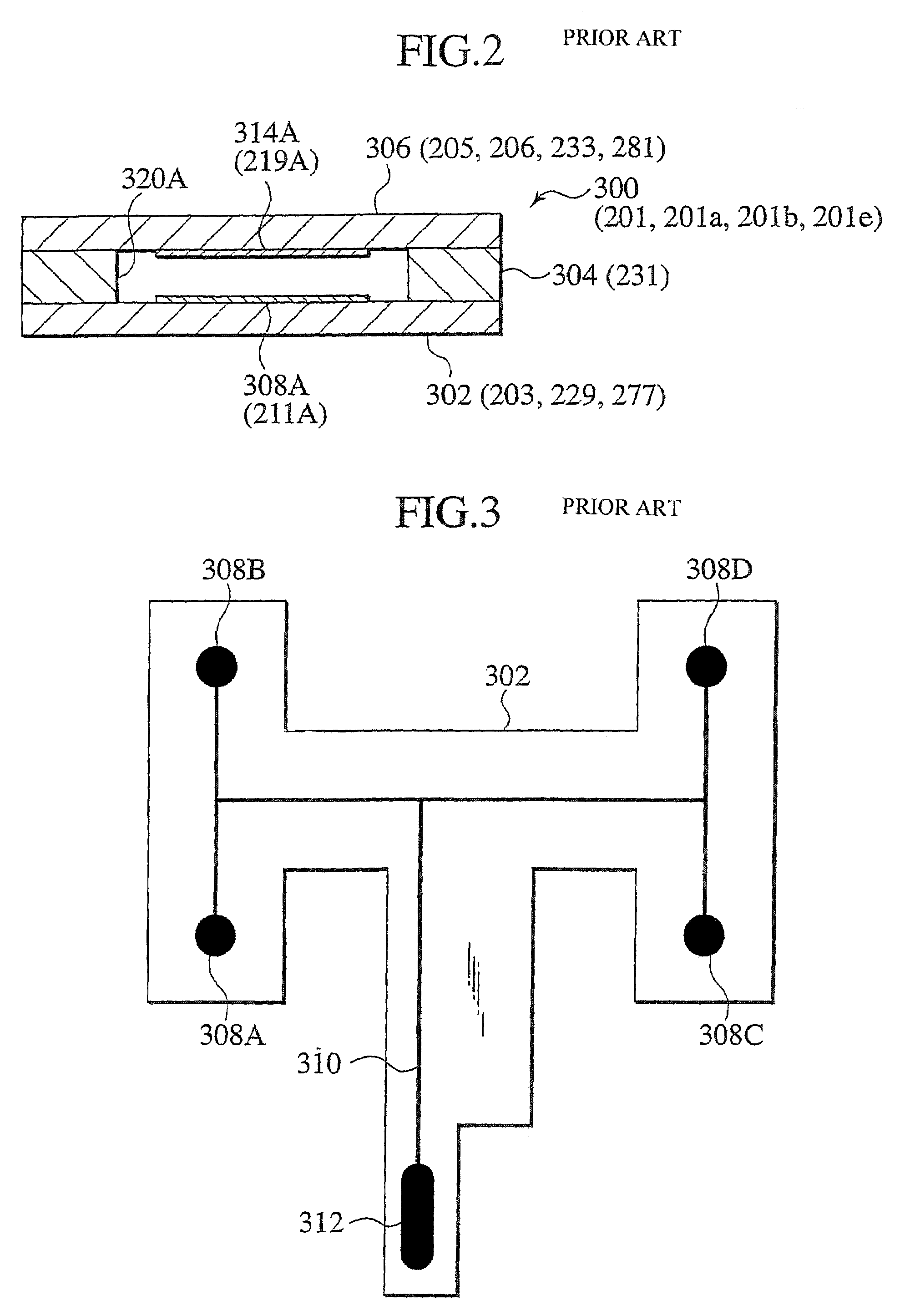
TECHNICAL FIELD[0001]The present invention relates to a seating detection switch for detecting whether or not a person has sat down in a seat, and more specifically, the present invention relates to a film-form seating detection switch providing a three layer construction of a film-form substrate, a film-form spacer and a film-form member superposed in this order.BACKGROUND ART[0002]Conventional film-form seating detection switches are known which are capable of detecting when a person has sat down in a seat, disclosed in for example Japanese Unexamined Patent Publication No. 9-315199 and Japanese Patent Publication No. 2909961. Such conventional seating detection switches comprise one electrode fixed to one surface of one film of a pair of films, electrically connected via one wire, another electrode fixed to the surface of the other film of the pair of films opposing the surface of the first film, electrically connected via one wire, and a spacer arranged between both those films ...

Claims


Application Information

Patent Timeline
Patent Type & Authority Patents(United States)
IPC IPC(8): H01H13/00B60N2/00B60N2/90H01H3/14H01H13/704
CPCB60N2/002B60R21/015H01H13/704H01H2231/026H01H2209/01H01H2209/012B60N2/0034B60N2/0021B60N2/0035B60N2/0025B60N2210/46
Inventor KAWAHIRA, TETSUYAISHII, TAKAHIROKOJIMA, MIKIHITOSHINDO, TOYOHIKOKUMAKIRI, NAOTAKAYOSHIFUKU, MASASHIFURUKAWA, TAKASHIKOYOTA, NOBUHIROTERASAKI, TSUTOMU
Owner THE FUJIKURA CABLE WORKS LTD
Learn More