Illuminated surgical retractor

a surgical retractor and illumination technology, applied in the field of surgical instruments, can solve the problems of inability to adapt to use in connection with functional instruments, current light delivery systems that do not provide optimal illumination, and current light delivery systems are costly to replace, so as to achieve the effect of quick and easy attachment and removal

Inactive Publication Date: 2007-12-11
LUMITEX INC
View PDF79 Cites 175 Cited by
  • Summary
  • Abstract
  • Description
  • Claims
  • Application Information

AI Technical Summary

Benefits of technology

[0010]In accordance with another aspect of the invention, the light delivery system is quickly and easily attached to and detached from an associated surgical instrument.

Problems solved by technology

While light delivery systems are generally known, prior art light delivery systems are not easily adapted for use in connection with functional instruments such as surgical instruments of various types.
In this respect, current light delivery systems do not provide optimal illumination for a variety of desired lighting conditions.
Moreover, current light delivery systems are costly to replace, and are thus not well suited for conditions which necessitate that the light delivery system be disposable, such as where sterilization is desired.

Method used


Image

  • Illuminated surgical retractor
  • Illuminated surgical retractor
  • Illuminated surgical retractor

Examples


Embodiment Construction

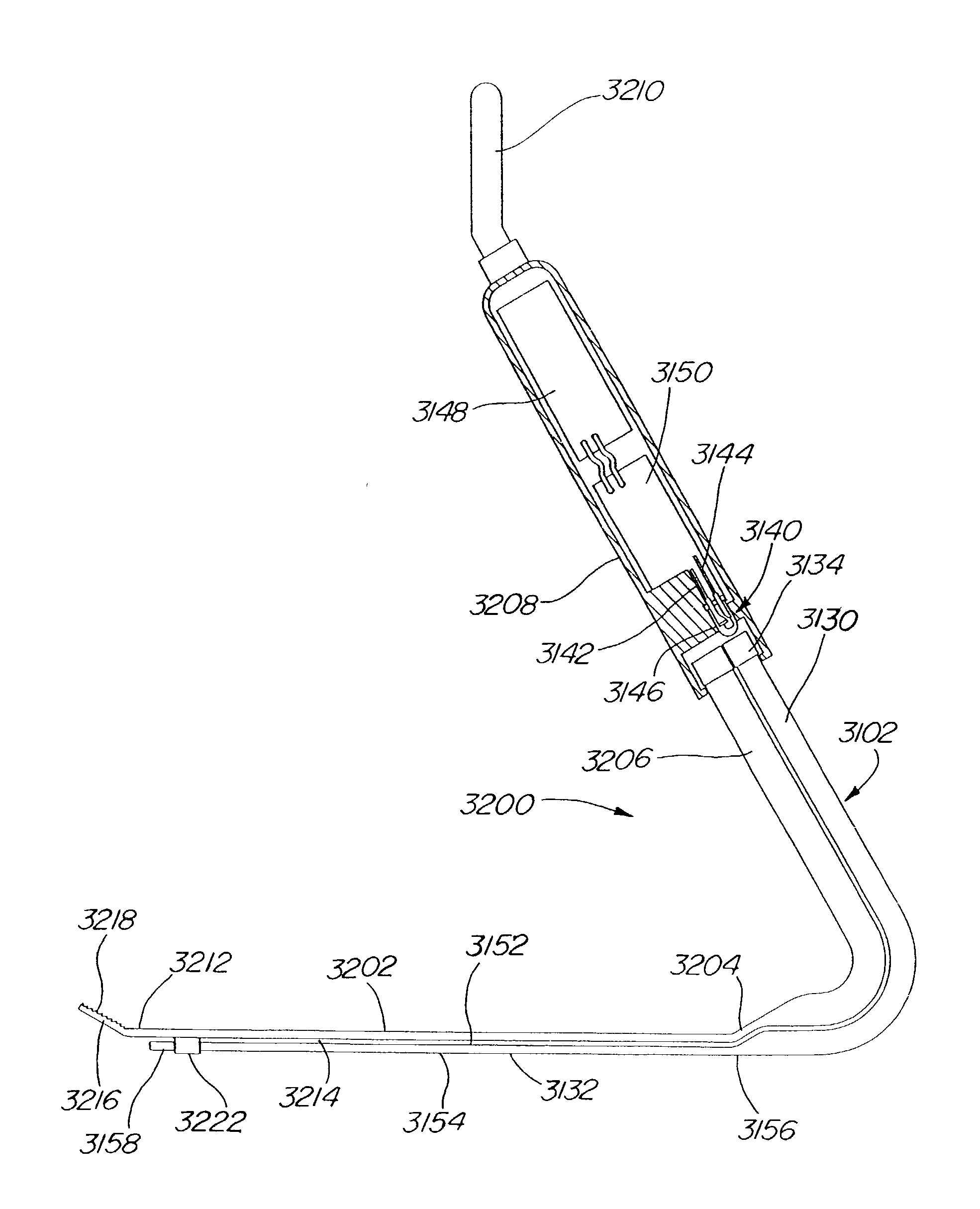
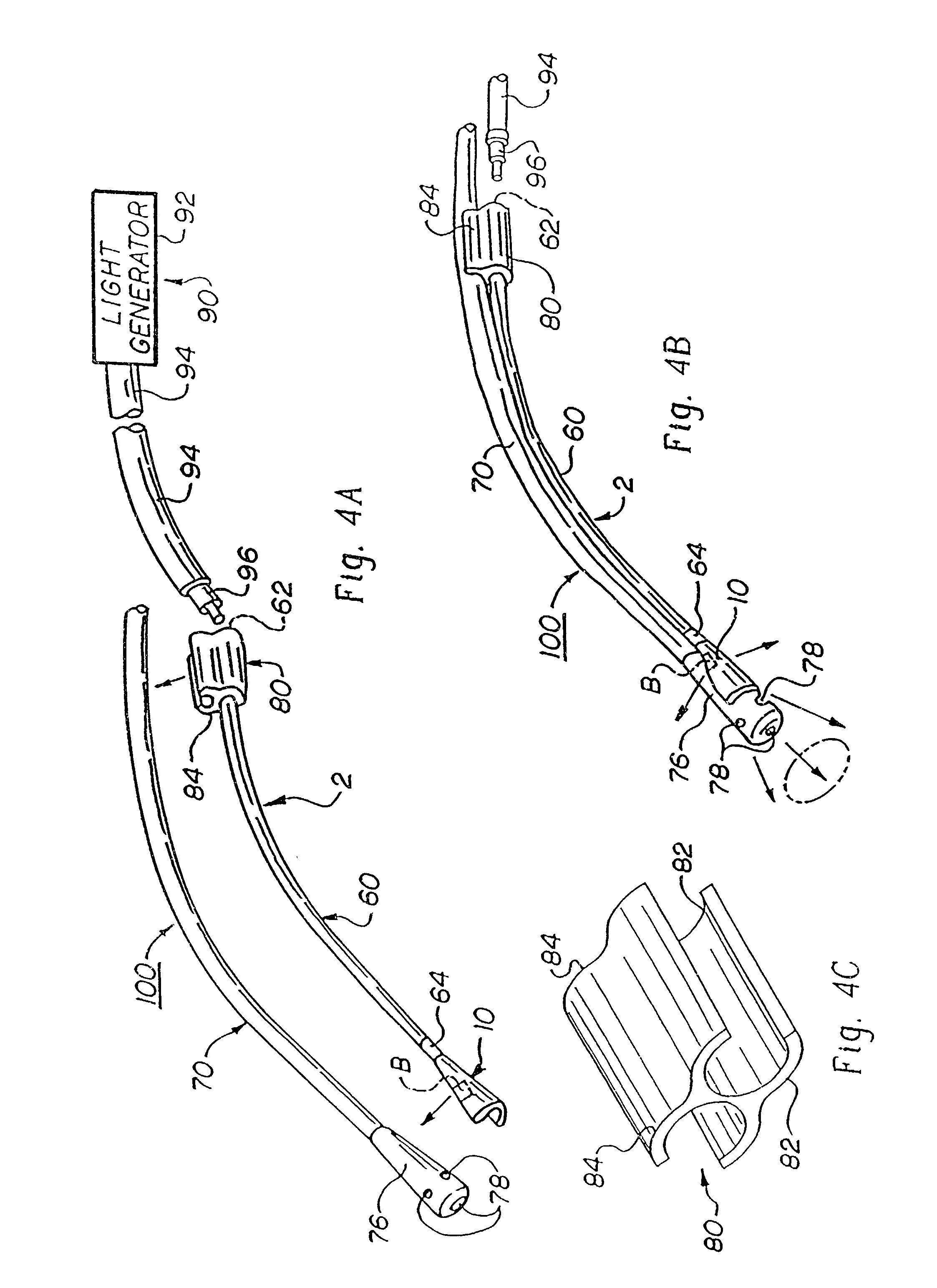
[0079]Referring now to the drawings wherein the showings are for the purposes of illustrating exemplary embodiments of the invention only and not for purposes of limiting same, FIGS. 4A and 4B illustrate a suction / blower device 100 having an externally mounted light delivery system 2. FIG. 4A shows a light delivery system 2 detached from suction / blower device 100, while FIG. 4B shows light delivery system 2 attached to suction / blower device 100. It should be appreciated that device 100 can take many forms including a surgical instrument or a conventional hand tool, as will be illustrated below.

[0080]Light delivery system 2 is generally comprised of a light emitter 10, a light distributor 60, and an attachment means 80. Light emitter 10 focuses light of varying intensity in a predetermined direction or pattern. As a result, an associated viewing field is illuminated with a predetermined light characteristic. Light distributor 60 (e.g., optic light pipe) transmits light from a light s...


PUM


Abstract

Illuminated surgical retractors include at least one retractor blade and a light delivery system. In some embodiments of the invention, the light delivery system includes a light emitter in the form of an elongated light emitting blade portion extending along the length of the retractor blade. The light emitter may be coupled to a light source integral with the retractor for illuminating all or a portion of the length of the light emitter or retractor blade. In other embodiments of the invention, the light delivery system may include an array of lights which may be attached directly to the retractor blade or to a support in the shape of an elongated blade that extends along the length of the retractor blade for illuminating all or a portion of the length of the retractor blade.

Description

RELATED APPLICATIONS[0001]The present invention is a continuation-in-part of U.S. application Ser. No. 09 / 735,104, filed Dec. 12, 2000, now U.S. Pat No. 6,504,985 which is a continuation of U.S. application Ser. No. 09 / 120,406, filed Jul. 22, 1998 (now U.S. Pat. No. 6,185,356), which is a continuation-in-part of U.S. application Ser. No. 08 / 886,666, filed Jul. 2, 1997 now abandoned . The contents of these applications are herein incorporated by reference.FIELD OF INVENTION[0002]The present invention relates generally to a surgical instrument that includes a light delivery system for providing illumination for the instrument.BACKGROUND OF THE INVENTION[0003]While light delivery systems are generally known, prior art light delivery systems are not easily adapted for use in connection with functional instruments such as surgical instruments of various types. In this respect, current light delivery systems do not provide optimal illumination for a variety of desired lighting conditions....

Claims


Application Information

Patent Timeline
Patent Type & Authority Patents(United States)
IPC IPC(8): A61B1/32A61B1/07A61B17/02A61B17/28A61B19/00F21V8/00G02B6/00
CPCA61B17/02A61B17/0218A61B17/0293A61B17/2812A61B19/52G02B6/0008G02B6/001G02B6/0036A61B1/0615G02B6/0061A61B17/0206A61B17/282A61B19/5202A61B2017/0243A61B2019/461A61B2019/5206A61B2019/521G02B6/0001G02B6/0038A61B1/07A61B90/36A61B90/30A61B2090/309A61B2090/061A61B2090/306
Inventor WILLIAMS, JEFFREY B.
Owner LUMITEX INC
Why Eureka
Try Eureka