Electronic balance having a vibration reducing mechanism

a technology of vibration reduction and electronic balance, applied in the field of electronic balance, can solve the problems of difficulty in arranging power point and supporting point in their ideal shape, and achieve the effect of reducing the influence of vibration

Inactive Publication Date: 2007-12-11
SHIMADZU CORP
View PDF9 Cites 19 Cited by
  • Summary
  • Abstract
  • Description
  • Claims
  • Application Information

AI Technical Summary

Benefits of technology

[0008]This invention is accomplished in view of such a circumstance. An object of this invention is to provide an electronic balance in which the influence of vibration in the width direction of the load measuring cell is reduced.
[0011]Further, in the electronic balance according to this invention, a spot facing is formed on a side portion in a longitudinal direction of the load measuring cell to decrease a width of the supporting-point spring.
[0013]The electronic balance according to this invention is constructed as described above, and can reduce influence of vibration in the thickness direction of the load measuring cell.

Problems solved by technology

Further, it was difficult to arrange the power point and the supporting point in their ideal shape, and implement the mechanical sensitivity in an optimum design.

Method used


Image

  • Electronic balance having a vibration reducing mechanism
  • Electronic balance having a vibration reducing mechanism
  • Electronic balance having a vibration reducing mechanism

Examples


Embodiment Construction

[0032]Now referring to the drawings, an explanation will be given of an embodiment of this invention.

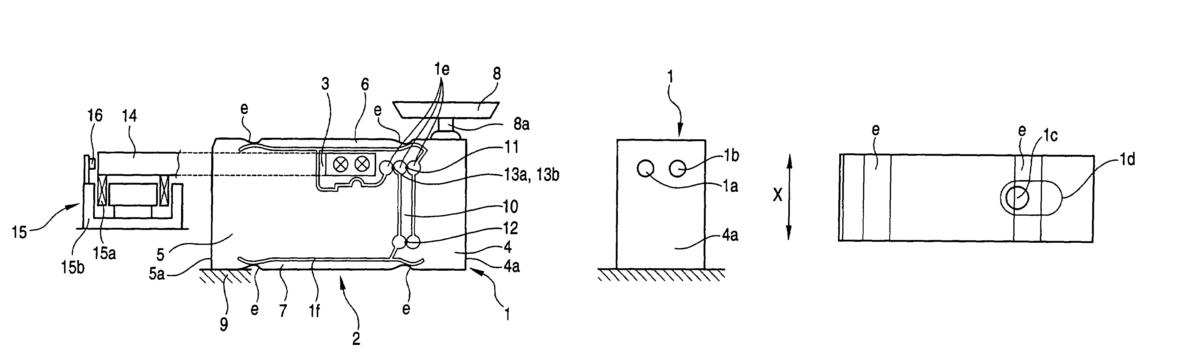
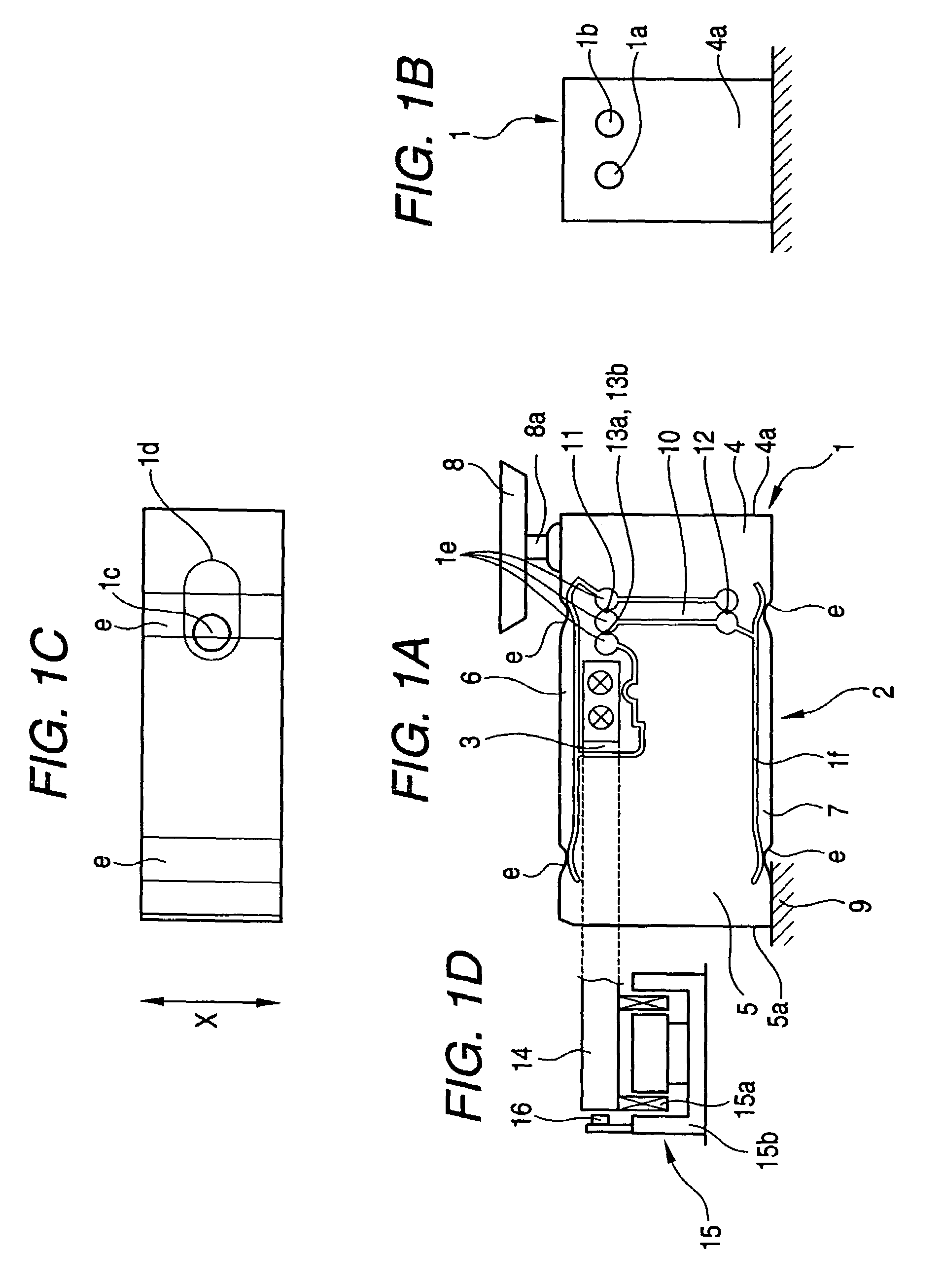
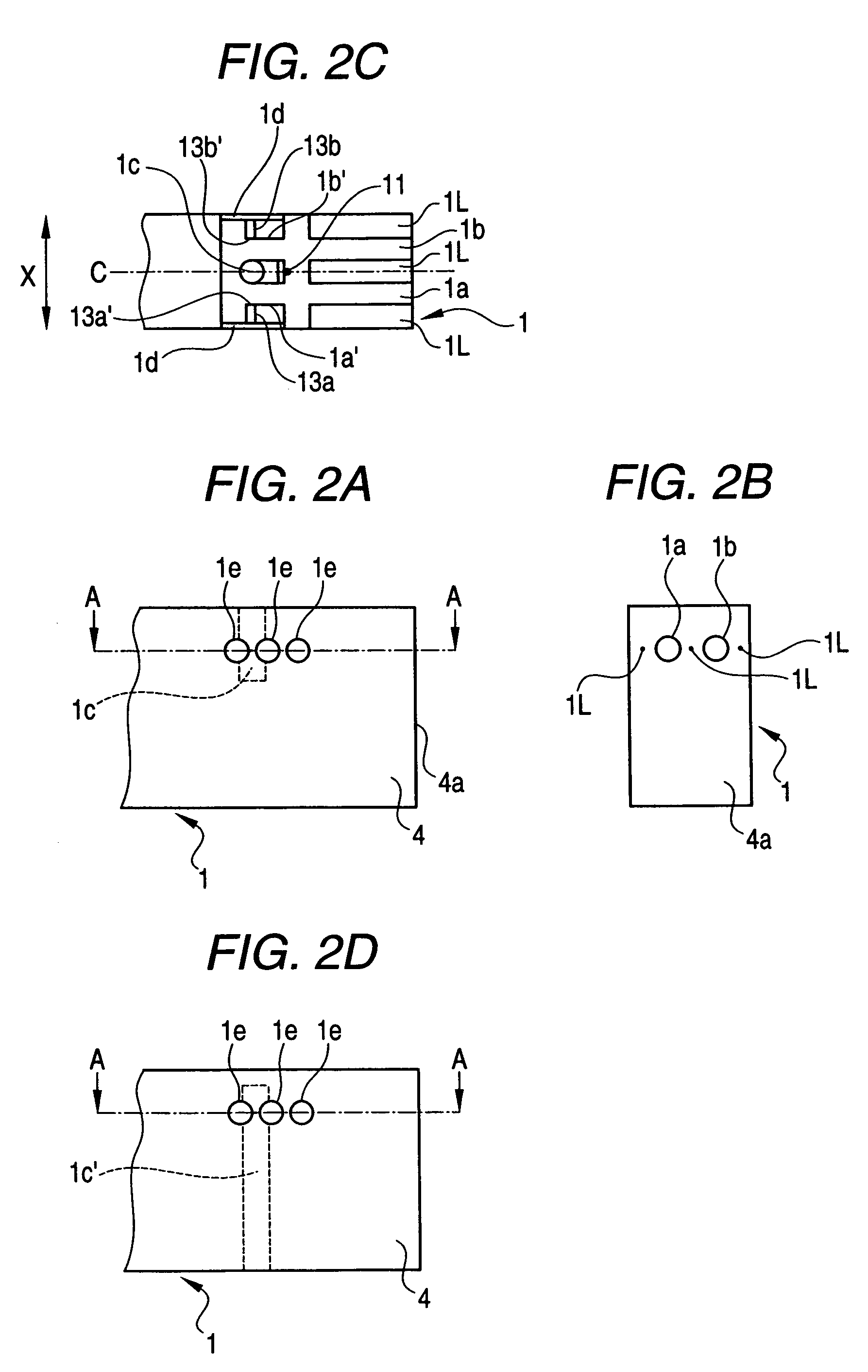
[0033]FIG. 1A is a side view of a load measuring cell 1 in the case of applying the invention to an electronic balance. FIG. 1B is a front view thereof in which a measuring pan 8 and a pan receiving stand 8a are not shown. FIG. 1C is a top view thereof in which the measuring pan 8 and the pan receiving stand 8a are not shown, and in which a spot facing 1d is shown. FIG. 1D is a partial sectional structural view of an electromagnetic force generating device 15. FIG. 2A is a partial sectional view showing positions of holes processed in the load measuring cell 1. FIG. 2B is a front view thereof, and FIG. 2C is a sectional view taken in line A-A. This load measuring cell 1 forms the following various holes by drilling in a unit block made of aluminum alloy and the like. Also, the load measuring cell 1 forms a Roverbal mechanism 2 and a lever block 3 by providing a slit 1f through wire e...


PUM


Abstract

Two horizontal holes are processed at the end face of a movable pillar of a load measuring cell in a block shape. A power-point spring is formed between the horizontal holes, and the internal side faces of the horizontal holes constitute the internal end faces of supporting-point springs. Further, from above or below the load measuring cell, a vertical hole is processed so that the supporting-point springs are separated by the vertical hole extending in a vertical direction and are formed on both side faces in the longitudinal direction of load measuring cell.

Description

[0001]This application claims foreign priority based on Japanese Patent application No. 2004-281877, filed Sep. 28, 2004, the contents of which is incorporated herein by reference in its entirety.BACKGROUND OF THE INVENTION[0002]1. Field of the Invention[0003]This invention relates to an electronic balance, and particularly to an electronic balance which is provided with a Roverbal mechanism (also called as a parallel guide), generates an electromagnetic force to eliminate displacement of a displaced portion due to a measuring load, and detects the measuring load from the generated electromagnetic force.[0004]2. Description of the Related Art[0005]In an electronic balance, generally, electromagnetic force is generated against the displacement of a sensor mechanism body due to measuring load, and the measuring load is measured on the basis of the electromagnetic force required for the displacement to be zero. As the sensor mechanism body in such electronic balance, a mechanism body p...

Claims


Application Information

Patent Timeline
Patent Type & Authority Patents(United States)
IPC IPC(8): G01G7/04
CPCG01G21/244
Inventor IIDUKA, ATUSHI
Owner SHIMADZU CORP
Why Eureka
Try Eureka