Light emitting diode driver circuit

a technology of driver circuit and light-emitting diodes, which is applied in the direction of electric variable regulation, process and machine control, instruments, etc., can solve the problems of increasing battery output, inefficient cost, and particularly egregious problems

Active Publication Date: 2007-12-11
MICREL
View PDF10 Cites 134 Cited by
  • Summary
  • Abstract
  • Description
  • Claims
  • Application Information

AI Technical Summary

Problems solved by technology

Problems can be particularly egregious for portable devices where battery output gradually decreases with time of use.
This also is cost inefficient.

Method used


Image

  • Light emitting diode driver circuit
  • Light emitting diode driver circuit
  • Light emitting diode driver circuit

Examples


Embodiment Construction

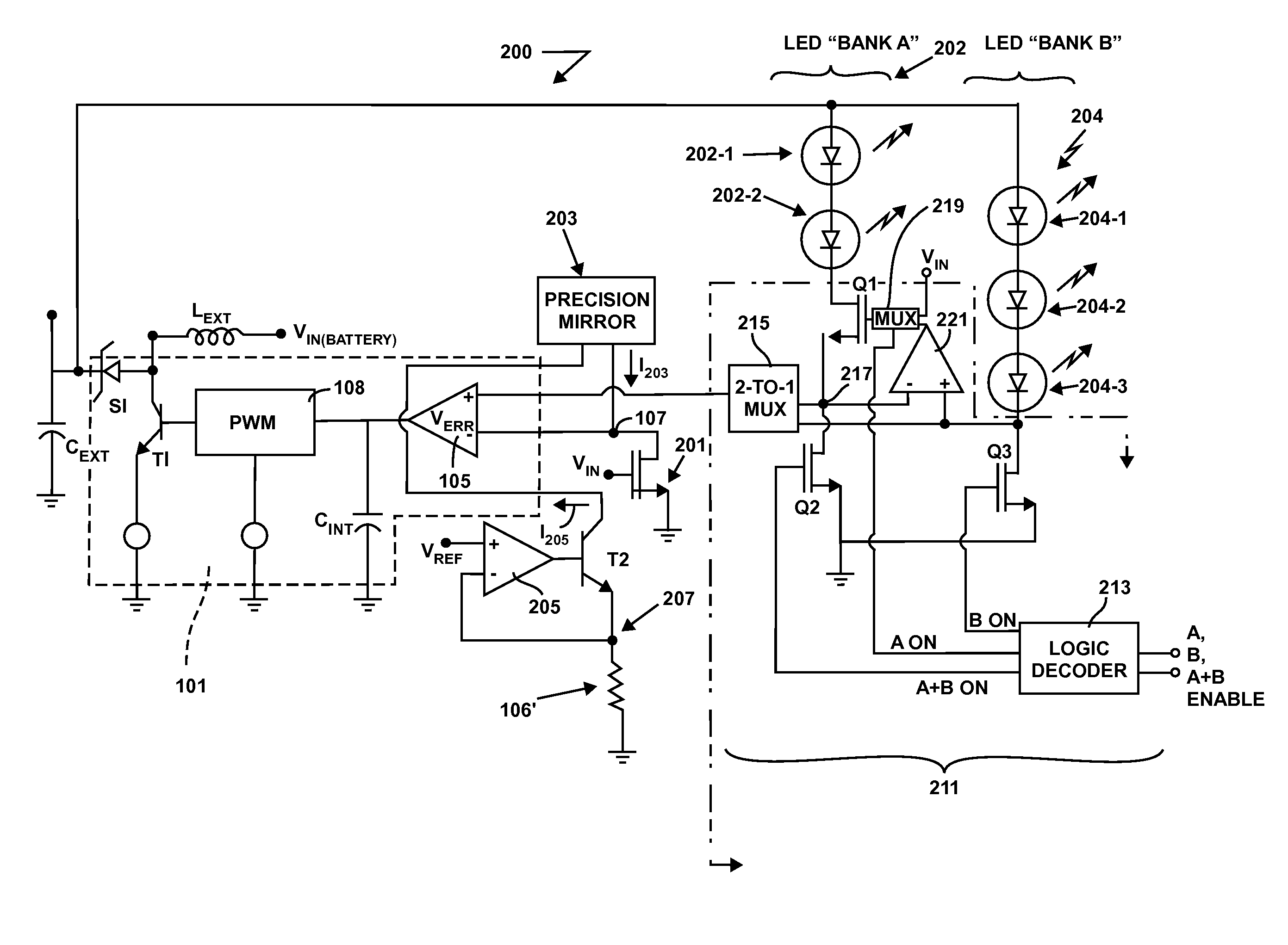
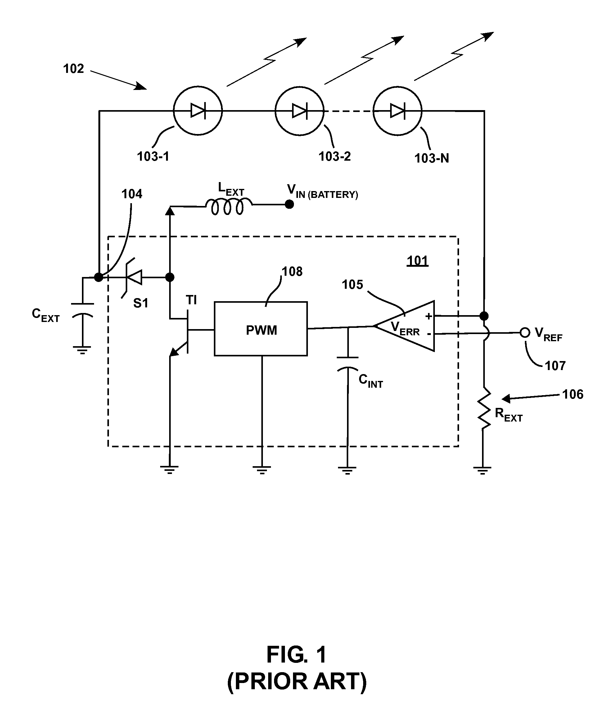
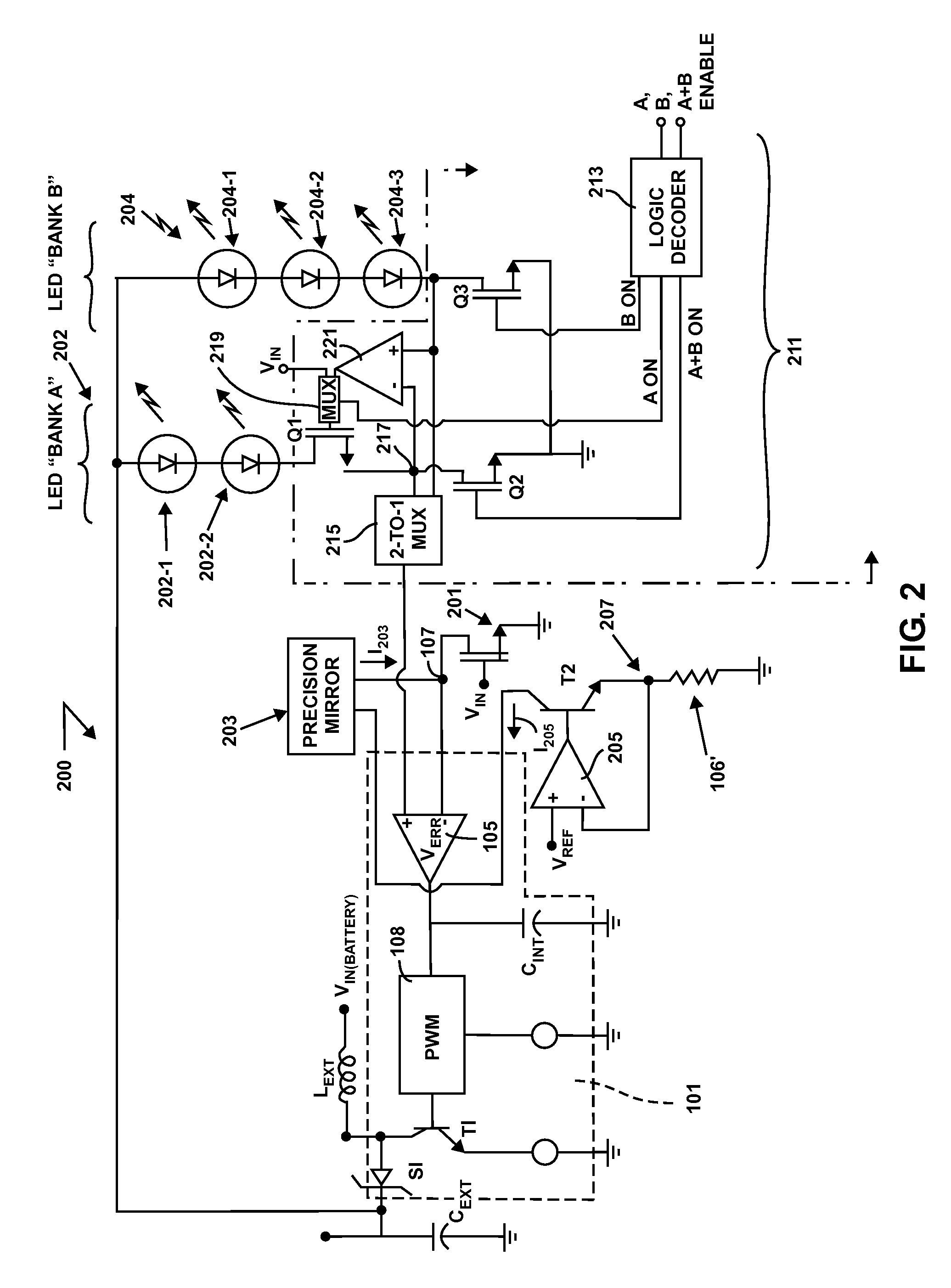
[0017]The present invention provides for a boost converter LED driver circuit using a single set of passive external LC components for controlling the current through, and thus the output of, one and more than one bank of LEDs. The present invention allows for regulated current in one and more than one bank of LEDs by sensing the voltage drop across a MOSFET operating in the linear region in the controller rather than sensing voltage across a resistor as in accordance with the conventional wisdom (e.g., as illustrated by FIG. 1 (Prior Art) described in the Background section hereinabove). In general, the output voltage of a switcher adjusts it's level automatically until the current to the LEDs is set to the desired LED threshold potential. An exemplary embodiment is described for a single switch-mode regulator using a single set of external passive elements which allows an OR or AND function for two banks of white LEDs. It will be recognized by those skilled in the art that the met...


PUM


Abstract

Describe is a device for a multiplexing, output current-sensed, boost converter circuit which may be used as an LED driver. A boost converter LED driver circuit using a single set of passive external LC components for controlling the current through, and thus the output of, one and more than one bank of LEDs. The present invention allows for regulated current in one and more than one bank of LEDs by sensing current in the controller. The output voltage of a switcher adjusts it's level automatically until the current to the LEDs is set to the desired LED threshold requirement.

Description

CROSS-REFERENCE TO RELATED APPLICATIONS[0001]Not applicable.STATEMENT REGARDING FEDERALLY SPONSORED RESEARCH OR DEVELOPMENT[0002]Not applicable.REFERENCE TO AN APPENDIX[0003]Not applicable.BACKGROUND[0004]1. Technical Field[0005]The technology described herein is generally related to the field of integrated circuits and, more particularly, to driver circuits for light emitting diode (“LED”) chains.[0006]2. Description of Related Art[0007]LEDs are known act as a source of emitted light for a wide variety of applications. LEDs are known to provide many advantages over incandescent and fluorescent illumination because of their long operating life, high efficiency, light weight, and low profile. LED light output is proportional to current therethrough. Problems can be particularly egregious for portable devices where battery output gradually decreases with time of use. Therefore, an LED driver circuit is needed that is relatively immune to small voltage fluctuations.[0008]Moreover, whit...

Claims


Application Information

Patent Timeline
Patent Type & Authority Patents(United States)
IPC IPC(8): G09G3/32G09G3/36H05B44/00
CPCH05B33/0815H05B33/0827Y02B20/347H05B45/46Y02B20/30H05B45/38
Inventor VINN, CHARLES
Owner MICREL
Why Eureka
Try Eureka