Disk drive suspension with limiter feature

Inactive Publication Date: 2007-12-11
MAGNECOMP
View PDF10 Cites 45 Cited by
  • Summary
  • Abstract
  • Description
  • Claims
  • Application Information

AI Technical Summary

Benefits of technology

[0008]It is an object of the invention therefore to provide an improved disk drive suspension. It is a further object to provide a disk drive suspension of the wireless type in which the flexible circuit comprising the trace conductors is used to define a flexure. A further object is to tether the flexure tongue laterally of the flexure tongue edges to limit undue tongue travel. Another object is to provide multiple points of attach

Problems solved by technology

Disk drive suspensions previously known tend to be too stiff for small form factor app

Method used


Image

  • Disk drive suspension with limiter feature
  • Disk drive suspension with limiter feature
  • Disk drive suspension with limiter feature

Examples


Embodiment Construction

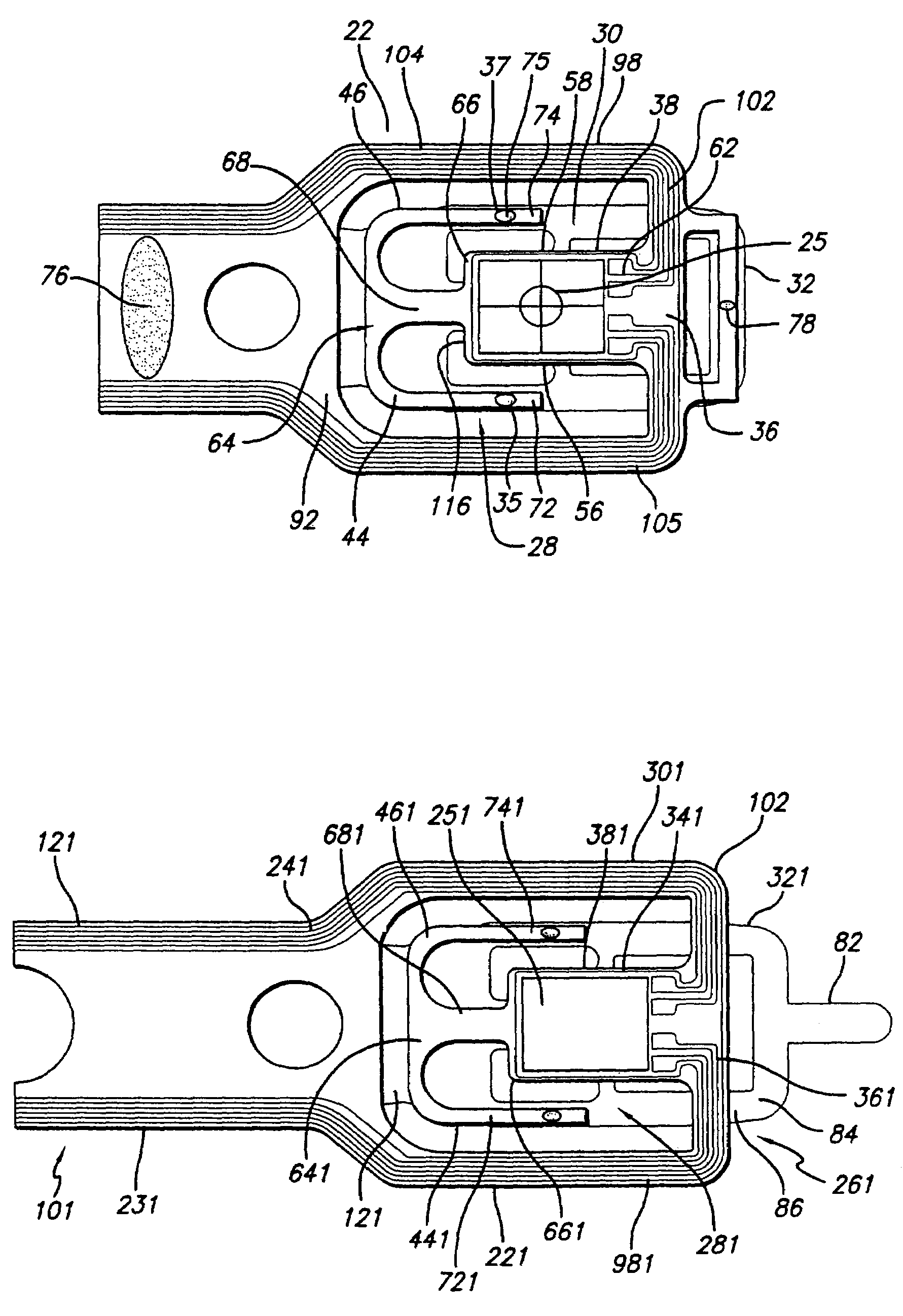
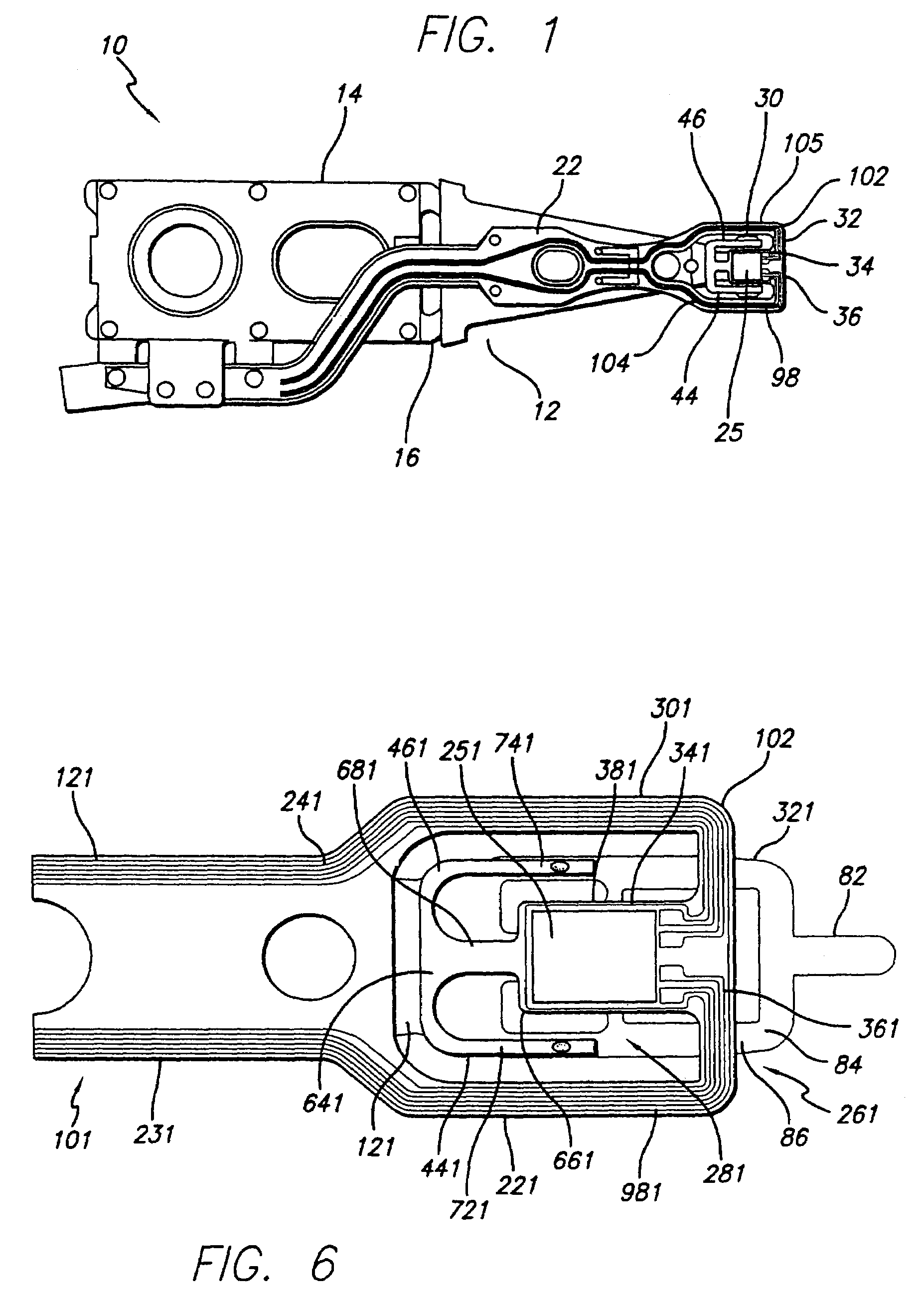
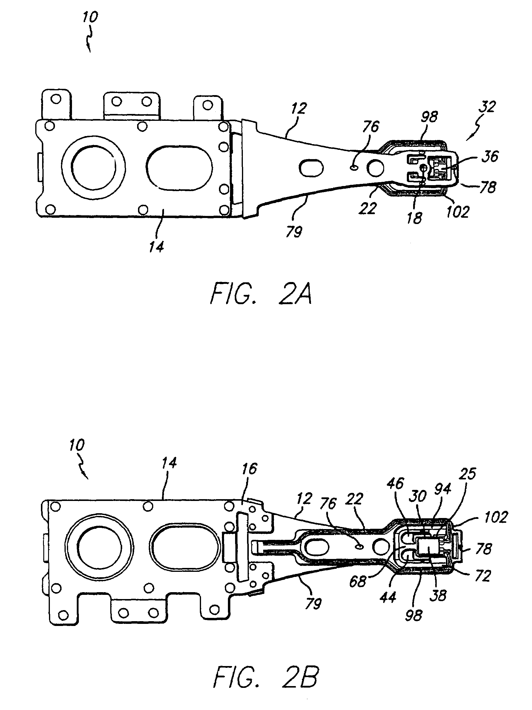
[0037]The invention uses added points of attachment laterally of the flexure to increase control over pitch and roll stiffness and have lower stiffness in very small suspensions such as femto form factor suspensions. The invention uses bonding legs from the flexure tongue area, generally formed from continued extents of the flexible circuit section in the tongue area, as anchors to adjust pitch and roll stiffness and also to act as a limiter structure for slider loading and unloading. Vertical and lateral shock damage to the suspension is prevented by the bonding leg anchors. Compared to conventional trace suspension assemblies, the present device does not require a stainless steel base layer. A flexible circuit is employed that uses no base layer, or preferably a copper metal layer or other metal or plastic base layer, an insulative film layer such as polyimide, and trace conductors such as copper traces. The copper base layer will typically be over-plated with gold or nickel / gold ...


PUM


Abstract

A disk drive suspension and method has a limiter structure that limits movement of the tongue relative to a surrounding frame by extending the plastic film layer and optionally the metal layer components of a flexure-defining flexible circuit laminate beyond the flexure tongue distal end and attaching the terminal regions of the extended components to the surrounding frame laterally of the tongue. The flexure-defining laminate is attached to the suspension rigid portion proximally and optionally distally as well as laterally with the limiter structure. A lift tip can be used to enable lifting of the suspension and to stiffen the suspension in lieu of the distal attachment of the flexible circuit.

Description

RELATED APPLICATIONS[0001]This application is a continuation of application Ser. No. 10 / 010,997 filed Nov. 30, 2001, now U.S. Pat. No. 6,757,137 issued Jun. 29, 2004, which application claims the benefit of Provisional Application Ser. No. 60 / 326,509, filed Sep. 30, 2001.STATEMENT REGARDING FEDERALLY SPONSORED RESEARCH OR DEVELOPMENT[0002]Not ApplicableREFERENCE TO A MICROFICHE APPENDIX[0003]Not ApplicableBACKGROUND OF THE INVENTION[0004]1. Field of the Invention[0005]This invention relates to disk drive suspensions, and more particularly to disk drive suspensions of the wireless type that use a flexible circuit supported by a rigid portion of a load beam or stiffener. The invention provides bonding legs laterally of the flexure portion of the suspension that are continued extents of the insulative plastic film or laminates of that film and a base layer for purpose of limiting lateral and vertical shock and thus damage. The continued extents turn reversely from the tongue distal end...

Claims


Application Information

Patent Timeline
IPC IPC(8): G11B21/21G11B21/22G11B5/48H05K1/18
CPCG11B5/4826G11B5/486H05K1/189
Inventor MEI, SHIJIN
Owner MAGNECOMP
Why Eureka
Try Eureka