Suspension interconnect with controlled noise

a suspension interconnect and controlled noise technology, applied in the direction of integrated arm assemblies, instruments, record information storage, etc., can solve the problems of degrading the integrity of signals being sent through trace conductors, and achieve the effect of improving disk drive suspension, reducing or eliminating the change in the distance between the traces and load beams, and reducing the effect of load beam spacing

Inactive Publication Date: 2005-12-13
MAGNECOMP
View PDF5 Cites 76 Cited by
  • Summary
  • Abstract
  • Description
  • Claims
  • Application Information

AI Technical Summary

Benefits of technology

[0008]It is an object of the present invention to provide an improved disk drive suspension. It is a further object to provide an electrical interconnect for a disk drive suspension having noise control, including control of cross talk set up in one trace by changes in impedance in an adjacent trace, through management of impedance variations by opposing the read and or write circuit pair members in a novel manner involving offset partly or fully of the opposed pair members. Other variations in impedance stemming from changes in the distance between the traces and load beam are reduced or eliminated by reducing the effect of the load beam spacing through the use of a grounding layer of metal at a fixed spacing from the trace conductors. In this way the trace conductors are maintained at a fixed spacing from a conductor although the traces are at varying spacing from the load beam. A further object includes providing a read or write pair of forward and return path conductive traces bracketing an insulative layer, such as a plastic film layer in which the pair members are relatively laterally offset to differentially control impedance between the pair members of the read and / or write pairs. A further object is control of the effects of load beam spacing through the use of a metal layer constantly spaced from the traces and spaced as well from the load beam. The objects of the invention thus include provision of an electrical interconnect geometry that enhances electrical coupling between the forward and return paths of a differential circuit thereby making it less sensitive to exterior factors, noise and cross-talk, provision of a geometry that allows enhancement of capacitive coupling between the forward and return paths of a differential circuit, thereby making possible the realization of very low impedance interconnects, provision of a vertically stacked interconnect geometry that allows more circuits to be packed in a given area, provision of a shield that is electrically commonly grounded with the load beam to nearby metallic objects and supports the interconnect structure and that maintains a constant spacing from the differential circuit, the shield protecting the differential circuits from impedance variations caused by a non-uniform attachment process with the metallic supports, such as load beams and arms, provision of ripple-free differential (characteristic) impedance through homogenous shielding and uniform trace cross-sectional geometry, provision of smooth (continuous) control of differential impedance by setting the offset parameter to the desired value, provision of impedance control in which changing the impedance of a certain differential pair does not significantly affect the impedance of adjacent pairs, and provision of a flexure through the interconnect assembly.

Problems solved by technology

These trace conductor pairs are subject to noise from reflected impedance variations that degrades the integrity of the signals being sent through the trace conductors.

Method used


Image

  • Suspension interconnect with controlled noise
  • Suspension interconnect with controlled noise
  • Suspension interconnect with controlled noise

Examples


Embodiment Construction

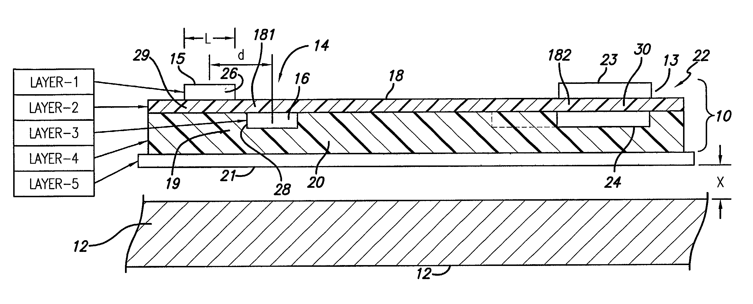
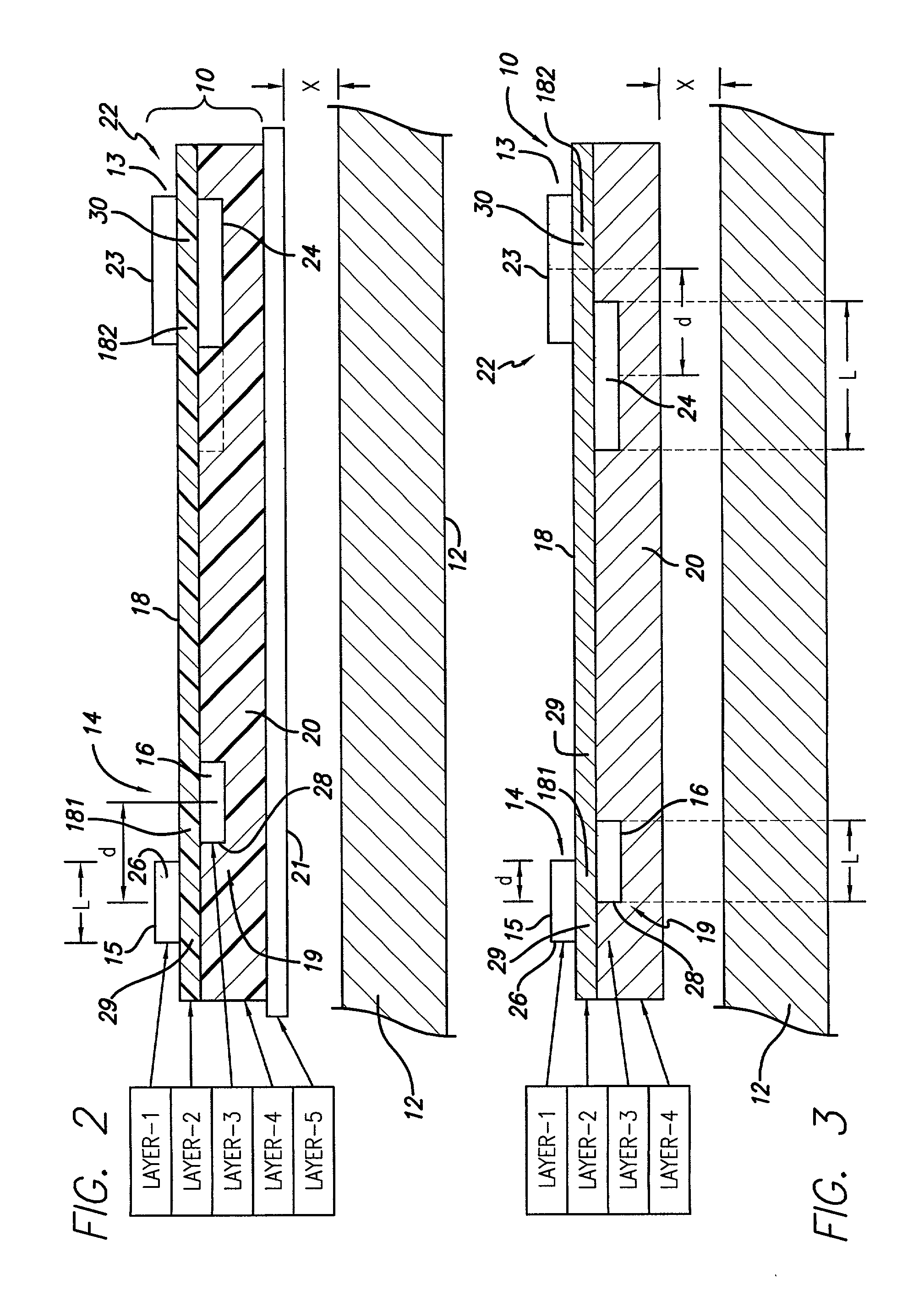
[0030]Disk drive interconnects supporting read and write channels demand controlled and constant impedance over the trace circuit path lengths between the pre-amplifier integrated circuit (IC) and the read-write (R / W) head.

[0031]For interconnects having multi-layered laminated structure, a common method for varying impedance has been by having present or not a metal sheet backing or support below the conductors at prescribed intervals. In a typical situation the write trace pair is required to have higher impedance than the read pair. The manufacturer uses “windowing” to provide a sequence of “backed” and “unbacked” portions create windowed sections, characterized by less or no metal backing, beneath the read and write traces.

[0032]It has been found, however, that the use of an arrangement of backed and un-backed portions causes local variations in impedance, this even where their spacing is kept smaller than the signal wavelength. Such fluctuations are not desirable.

[0033]As is kno...


PUM

PropertyMeasurementUnit
impedanceaaaaaaaaaa
impedanceaaaaaaaaaa
conductiveaaaaaaaaaa

Abstract

A disk drive suspension and method has a metal load beam and an electrical interconnect assembly. The interconnect assembly has an insulative layer, a read pair of forward and return path conductive traces, a write pair of forward and return path conductive traces that are supported by the insulative layer, preferably in offset relation across the insulative layer, and a metal layer for grounding and mounted on the insulative plastic layer in fixed spaced relation to the conductive traces to be between the interconnect assembly and the load beam. The metal layer shields the conductive traces from variations in impedance occasioned by varying distances between said electrical interconnect and said load beam.

Description

CROSS-REFERENCE TO RELATED APPLICATIONS[0001]This application claims the benefit of U.S. Provisional Application Ser. No. 60 / 376,977 filed Apr. 30, 2002.STATEMENT REGARDING FEDERALLY SPONSORED RESEARCH OR DEVELOPMENT[0002]Not ApplicableREFERENCE TO A MICROFICHE APPENDIX[0003]Not ApplicableBACKGROUND OF THE INVENTION[0004]1. Field of the Invention[0005]This invention relates to disk drive suspensions, and more particularly to disk drive suspensions including an electrical interconnect assembly adapted to be supported on a load beam, and to interconnect assemblies in combination with a load beam. The invention suspensions and interconnect assemblies provide enhanced performance through the optimized control of noise caused by impedance differences along the interconnect by spacing laterally the normally vertically superimposed signal forward and return paths of the read or write circuits, and, in some cases, adding a grounding layer between the conductive traces and the load beam.[000...

Claims


Application Information

Patent Timeline
Patent Type & Authority Patents(United States)
IPC IPC(8): G11B5/48H05K1/02
CPCG11B5/486H05K1/0218H05K3/0061H05K2201/0715H05K2201/09672G11B5/484
Inventor KULANGARA, SIVADASANKHAN, AMANULLAH
Owner MAGNECOMP
Why Eureka
Try Eureka