Loading-protected bending microactuator in additive suspensions

a microactuator and additive technology, applied in the field of microactuation suspensions, can solve the problems of limited adoption of these ideas in the field of disk drive suspensions, and achieve the effects of reducing the cost of electrical connection, free, and improving the suspension of disk drives

Active Publication Date: 2008-12-02
MAGNECOMP
View PDF10 Cites 99 Cited by
  • Summary
  • Abstract
  • Description
  • Claims
  • Application Information

AI Technical Summary

Benefits of technology

[0006]There is a need to provide an effective bending motor for disk drive suspensions that is economical, simple, and free of the damage potential that is found in the prior art. It is an object of the present invention therefore to provide and improved disk drive suspension. It is a further object to provide an improved disk drive suspension that uses but a single bending motor PZT. A further object is to laterally relatively shift respective suspension portions for slider placement opposite a disk track using the single PZT free of added pivot structure. A further object is to simplify and thus lower the cost of electrical connection to the PZT. Yet another object is to provide indicia on the PZT enabling visual determination of correct polarity a feature combinable with dividing the PZT asymmetrically rather than symmetrically. A further object is to provide a single PZT having one common ground electrical connection and at least two opposing connections to enable bending of the PZT by appropriate application of suitable sign voltages relative to the predetermined polarity of the PZT portions. A further object is application of a single polarity voltage to an oppositely direction poled pair of PZT portions for bimorph response of bending, or application of a positive or negative voltage to like pole direction paired portions for a bimorph response of bending.

Problems solved by technology

Complex proposed structures and a failure to take properly into account the frailty of the bending motors have limited the adoption of these ideas in disk drive suspensions.

Method used


Image

  • Loading-protected bending microactuator in additive suspensions
  • Loading-protected bending microactuator in additive suspensions
  • Loading-protected bending microactuator in additive suspensions

Examples


Embodiment Construction

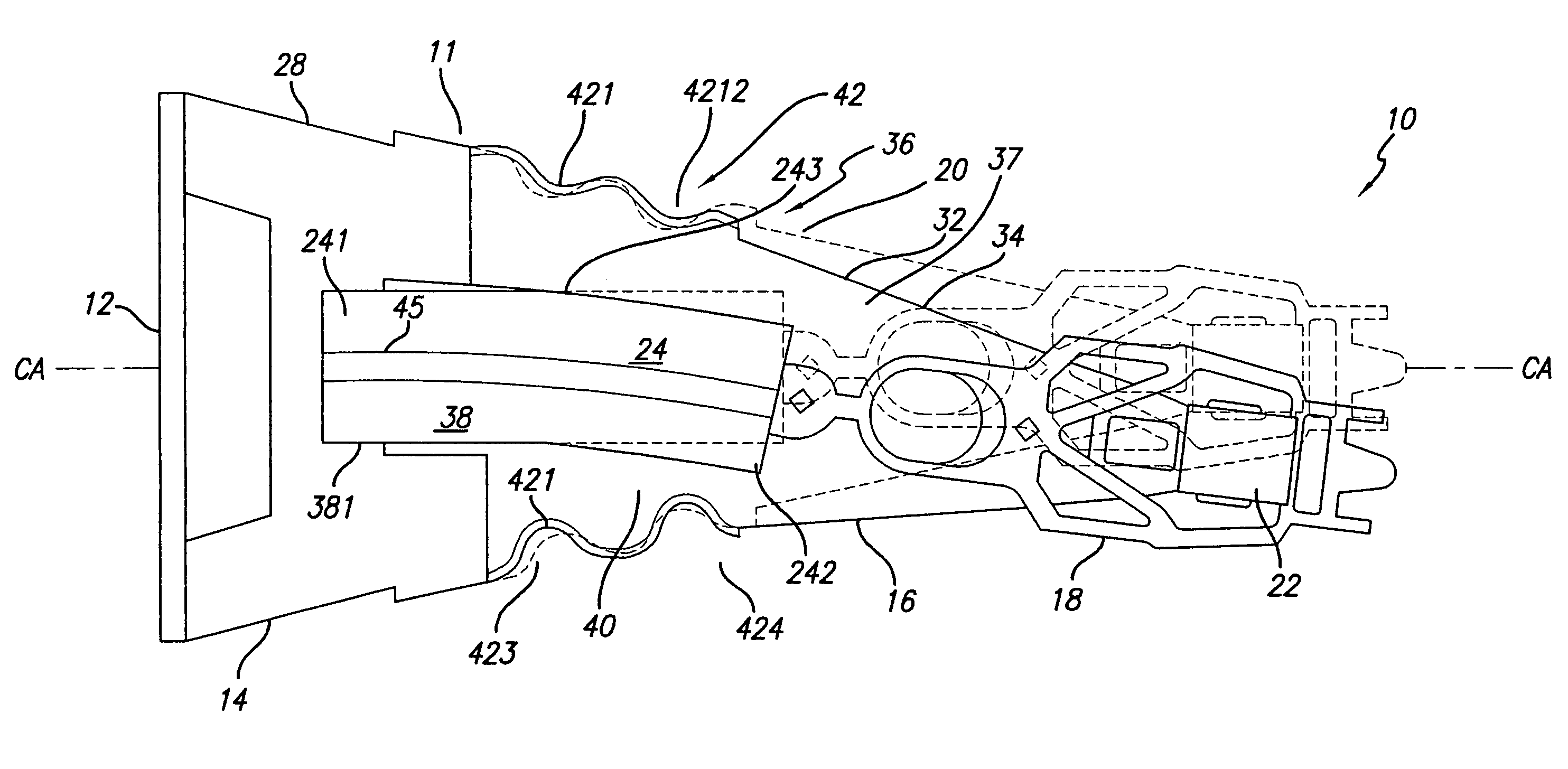
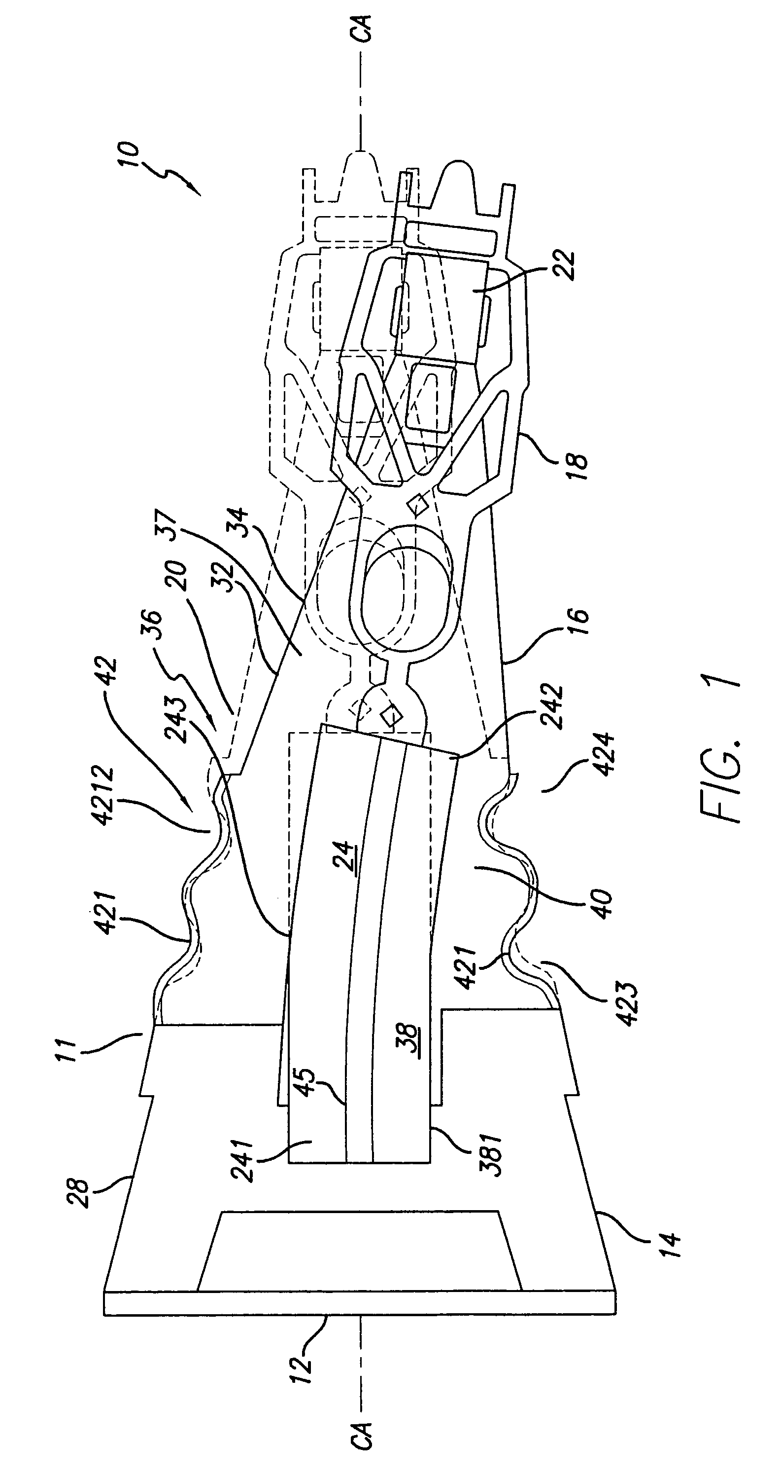
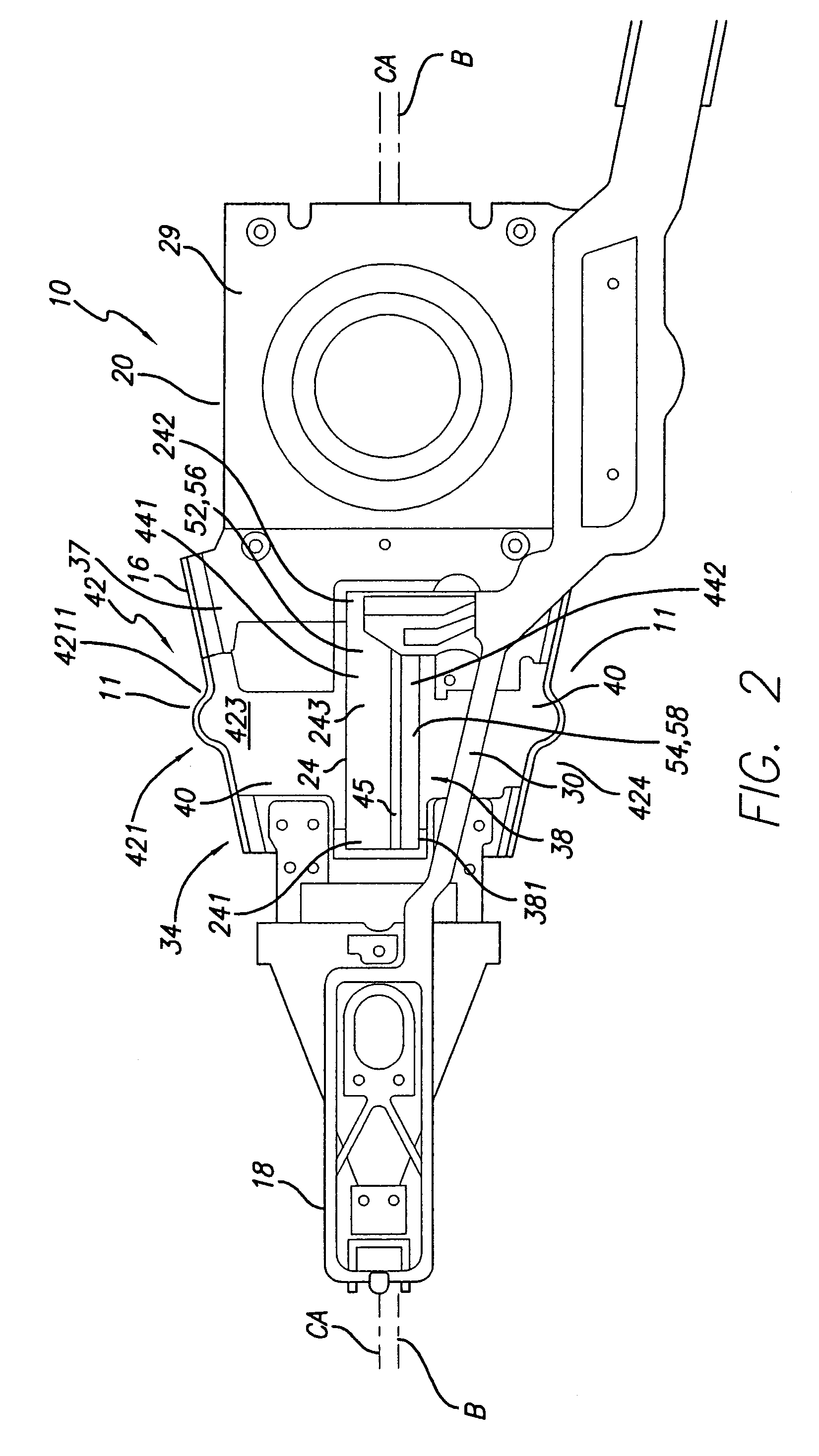
[0034]The invention overcomes the prior art difficulties of employing a single differentially responsive bending motor in effective microactuation of a disk drive suspension, e.g. by having the bending portion of motor unsupported and untrammeled by attachment to a support, and protecting the unsupported bending motor portion with a load assist structure, typically suspension edges, preferably in the form of edge runners or rails having localized deflection in various forms to preferentially bend laterally with the bending motor while being stiff to vertical bending to block undue loading of the bending motor by preferentially taking a major part of the loading themselves. While the invention will be described primarily with reference to PZT (lead zirconate titanate) bending motors, other bending motor structures such as those based on other electroactive chemicals, ceramics or polymers, or based on electrostrictive materials can be used.

[0035]Like prior art PZT microactuation devic...


PUM


Abstract

A microactuated disk drive suspension for supporting a slider at a disk includes a load beam extending in a plane and having on a common axis a base section adapted for mounting to an actuator, a spring section and a beam section carrying a flexure and the slider thereon. The suspension has relatively movable proximate and distal portions on the common axis that are joined by a bending system cantilevered from the proximate portion and including a cantilevered bending motor opposed to the common axis and having a laterally bendable unsupported region. A cantilevered laterally bendable load assist structure defined by the suspension edges is provided arranged to block undue loading of the bending motor unsupported region.

Description

CROSS-REFERENCE TO RELATED APPLICATIONS[0001]This application claims the benefit of U.S. Provisional Application Ser. No. 60 / 780,179, filed Mar. 6, 2006, further claims the benefit of U.S. Provisional Application Ser. No. 60 / 813,543, filed Jun. 13, 2006, and still further claims the benefit of U.S. Provisional Application Ser. No. 60 / 832,547, filed Jul. 20, 2006.BACKGROUND OF THE INVENTION[0002]1. Field of the Invention[0003]This invention relates to disk drive suspensions, and more particularly to microactuated suspensions in which a bending motor such as a differentially polarized single PZT having an unsupported bending region is used to finely position the slider at a disk.[0004]2. Description of the Related Art[0005]Bimorphs are shown in U.S. Pat. No. 3,447,217 to Kumada and U.S. Pat. No. 5,850,109 to Mock et al; the use of bimorphs and bending motors employing bimorphs for minute shifts of relatively moving parts is shown in U.S. Pat. No. 4,367,504 to Seki and others. Use of b...

Claims


Application Information

Patent Timeline
Patent Type & Authority Patents(United States)
IPC IPC(8): H01L41/08
CPCG11B5/4833G11B5/4873G11B5/5552
Inventor MEI, SHIJINMISUTA, STEVE
Owner MAGNECOMP
Why Eureka
Try Eureka