Moving picture coding method and moving picture decoding method

a coding method and a technology for moving pictures, applied in the field of moving picture coding methods and moving picture decoding methods, can solve the problems of increasing the amount of linear prediction processing, the inability to generate optimal predictive images, etc., and achieve the effect of improving coding efficiency and reducing processing costs

Active Publication Date: 2007-12-11
GK BRIDGE 1
View PDF4 Cites 54 Cited by
  • Summary
  • Abstract
  • Description
  • Claims
  • Application Information

AI Technical Summary

Benefits of technology

[0033]Against this backdrop, it is an object of the present invention to provide a picture coding method and a picture decoding method and apparatuses and programs for executing these methods for allowing assignment of a plurality of reference indices to one reference picture and thus improving decoding efficiency of reference indices in both cases where a plurality of reference indices are assigned and one reference index is assigned.

Problems solved by technology

There is no problem if images change uniformly in a picture as a whole, but there is a high possibility that the optimum predictive image cannot be generated if respective images change differently.
In addition, there is another problem that the amount of processing for linear prediction increases because the equation includes multiplications.

Method used


Image

  • Moving picture coding method and moving picture decoding method
  • Moving picture coding method and moving picture decoding method
  • Moving picture coding method and moving picture decoding method

Examples


first embodiment

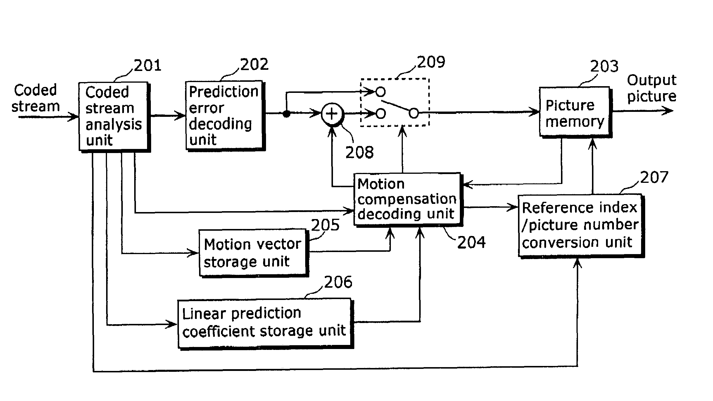
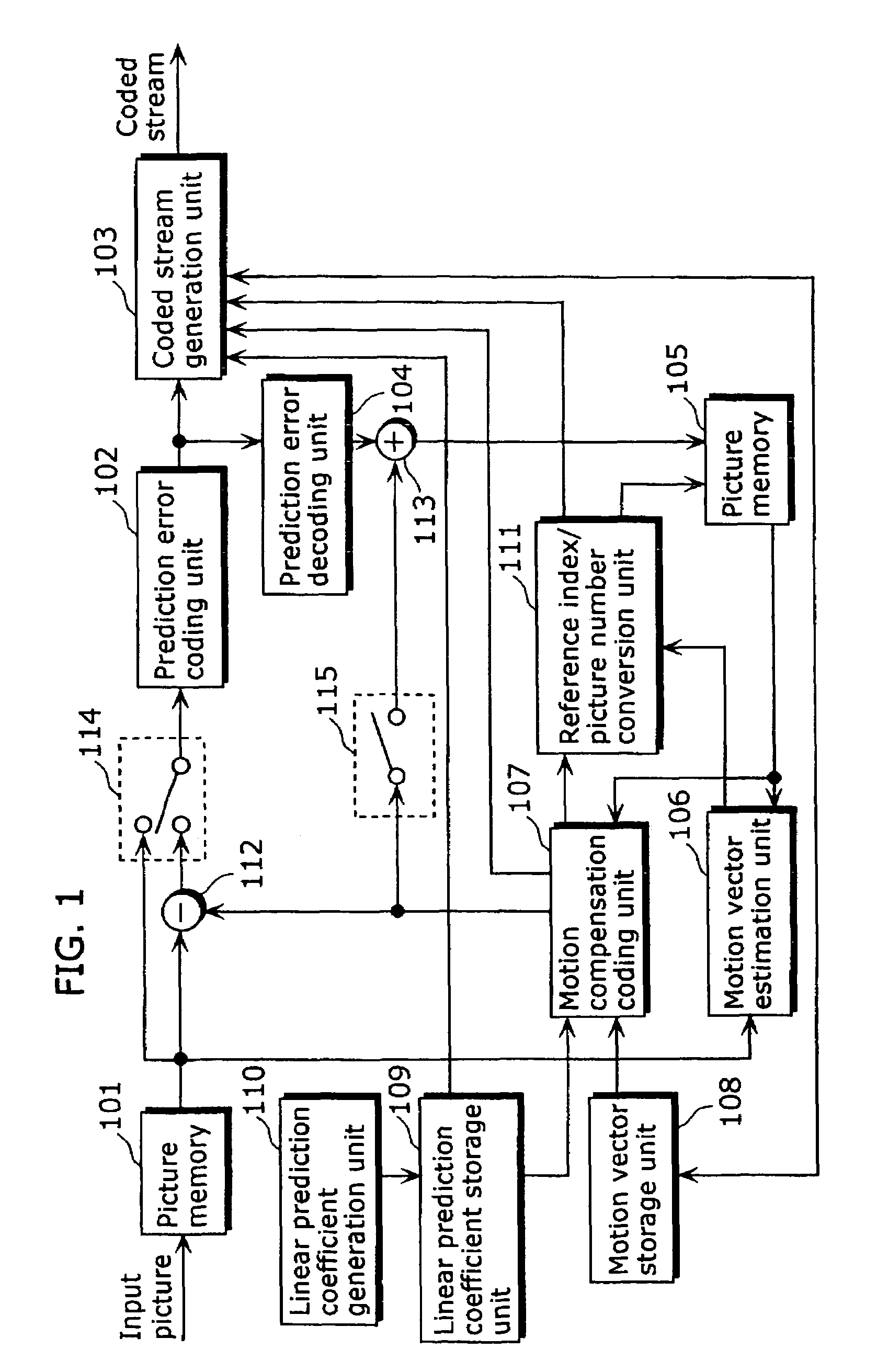
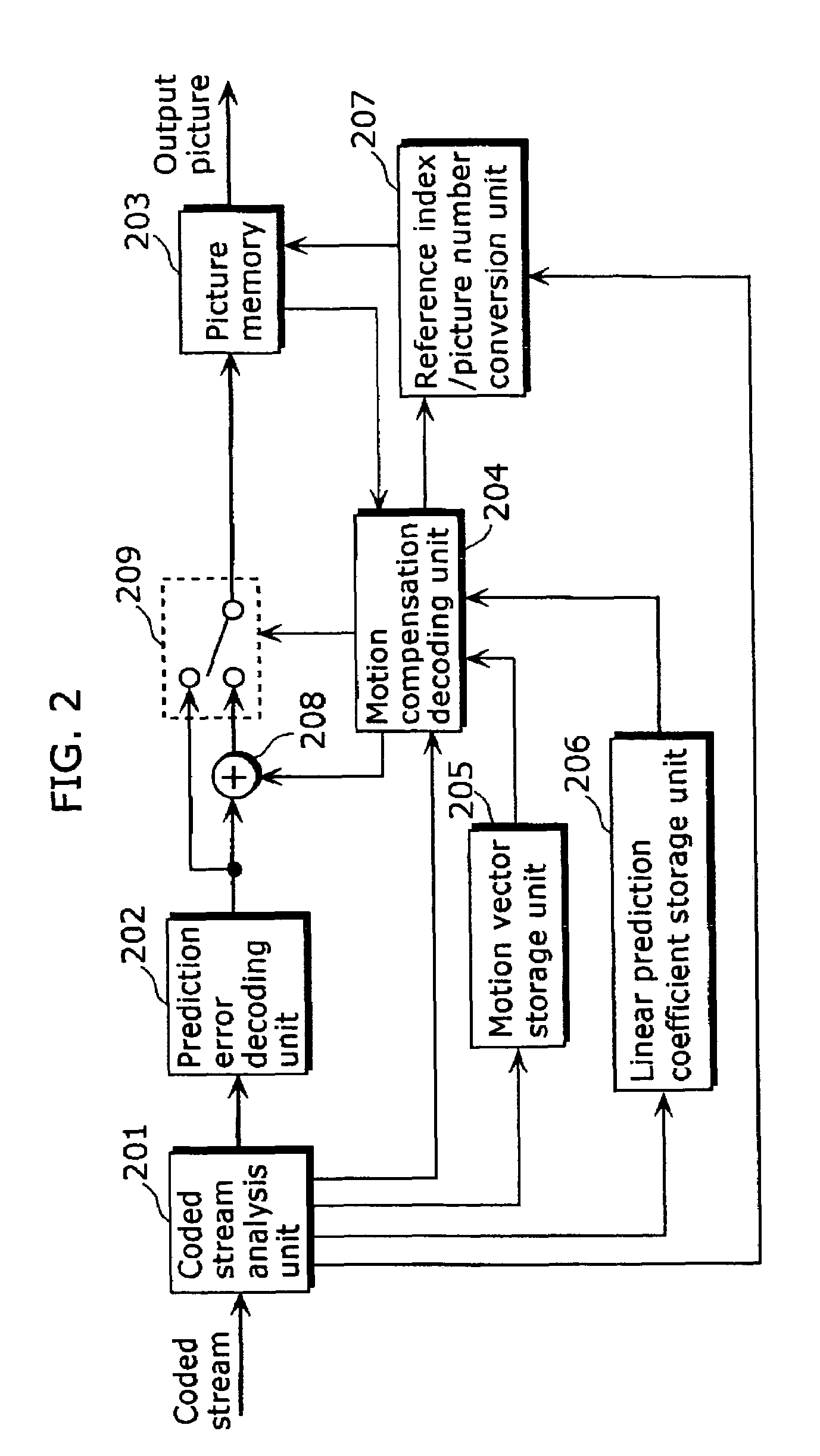
[0133]FIG. 1 is a block diagram showing a structure of a moving picture coding apparatus in the first embodiment of the present invention. The moving picture coding method executed in this moving picture coding apparatus, specifically, (1) an overview of coding, (2) a method for assigning reference indices and (3) a method for generating a predictive image, will be explained in this order using the block diagram as shown in FIG. 1.

[0134](1) Overview of Coding

[0135]A moving picture to be coded is inputted to a picture memory 101 on a picture-by-picture basis in display order, and the inputted pictures are reordered into coding order. FIGS. 31A and 31B are diagrams showing an example of reordering of pictures. FIG. 31A shows an example of pictures in display order, and FIG. 31B shows an example of the pictures reordered into coding order. Here, since pictures B3 and B6 refer both temporally preceding and subsequent pictures, the reference pictures need to be coded before coding these ...

second embodiment

[0223]The moving picture coding method in the second embodiment of the present invention will be explained. Since the structure of the coding apparatus, the flow of coding processing and the reference index assignment method are exactly the same as those in the first embodiment, the explanation thereof is not repeated here.

[0224]In the first embodiment, linear prediction is performed on each pixel for generating a predictive image in motion compensation using the equation 1, the equation 3 or the equation 4. However, since all of these equations include multiplications, which cause significant increase of processing amount in considering that these multiplications are performed on all the pixels.

[0225]So, it is possible to use the equation 5 instead of the equation 1, the equation 6 instead of the equation 3, and the equation 7 instead of the equation 4. These equations allow calculations only using bit shift operations without using multiplications, and thus allows reduction of pro...

third embodiment

[0247]The moving picture coding method in the third embodiment of the present invention will be explained. Since the structure of the coding apparatus, the flow of coding processing and the reference index assignment method are exactly same as those in the first embodiment, the explanation thereof is not repeated here.

[0248]As explained in the background art, there is a method for generating a predictive image using a predetermined fixed equation such as the equation 2a and the equation 2b, unlike the first and second embodiments in which a predictive image is generated using a prediction equation obtained from weighting coefficient sets of linear prediction coefficients. This conventional method has an advantage that a data amount for coding can be reduced because there is no need to code and transmit the weighting coefficient sets used for generating the predictive image. Also, the processing amount for linear prediction can be significantly reduced because the equations for linea...


PUM


Abstract

According to a picture coding method of the present invention, a coded picture identified by a picture number is stored, as a reference picture, into a storage unit; commands indicating correspondence between picture numbers and reference indices for designating reference pictures and coefficients used for generation of predictive images are generated; a reference picture being used when motion compensation is performed on a current block in a current picture to be coded is designated by a reference index; a predictive image is generated by performing linear prediction on a block being obtained by motion estimation within the designated reference picture, by use of a coefficient corresponding to the reference index; a coded image signal including a coded signal obtained by coding a prediction error being a difference between the current block in the current picture to be coded and the predictive image, the commands, the reference index and the coefficient is outputted. At that time, information indicating the maximum reference index value is coded and included into the coded image signal, and the commands indicating correspondence between at least one picture number and a plurality of reference indices are generated.

Description

TECHNICAL FIELD[0001]The present invention relates to a moving picture coding method and a moving picture decoding method, and particularly to a coding method and a decoding method using inter-picture prediction with reference to previously coded pictures.BACKGROUND ART[0002]With the development of multimedia applications, it has become popular to handle integrally all kinds of media information such as video, audio and text. For that purpose, digitalization of all these kinds of media allows handling of them in an integral manner. However, since digitized images have an enormous amount of data, image information compression techniques are absolutely essential for storage and transmission of such information. It is also important to standardize such compression techniques for interoperation of compressed image data. There exist international standards for image compression techniques, such as H.261 and H.263 standardized by International Telecommunication Union - Telecommunication S...

Claims


Application Information

Patent Timeline
Patent Type & Authority Patents(United States)
IPC IPC(8): G06T9/00H04N7/32H04N7/64G06K9/36H04N19/89
CPCH04N19/00763H04N19/577H04N19/176H04N19/70H04N19/147H04N19/172H04N19/46H04N19/134H04N19/61H04N19/117H04N19/18H04N19/42H04N19/573H04N19/58H04N19/105H04N19/174H04N19/51H04N19/103H04N19/137H04N19/139H04N19/159H04N19/177H04N19/182H04N19/593
Inventor ABE, KIYOFUMIKADONO, SHINYAKONDO, SATOSHIHAGAI, MAKOTO
Owner GK BRIDGE 1
Why Eureka
Try Eureka