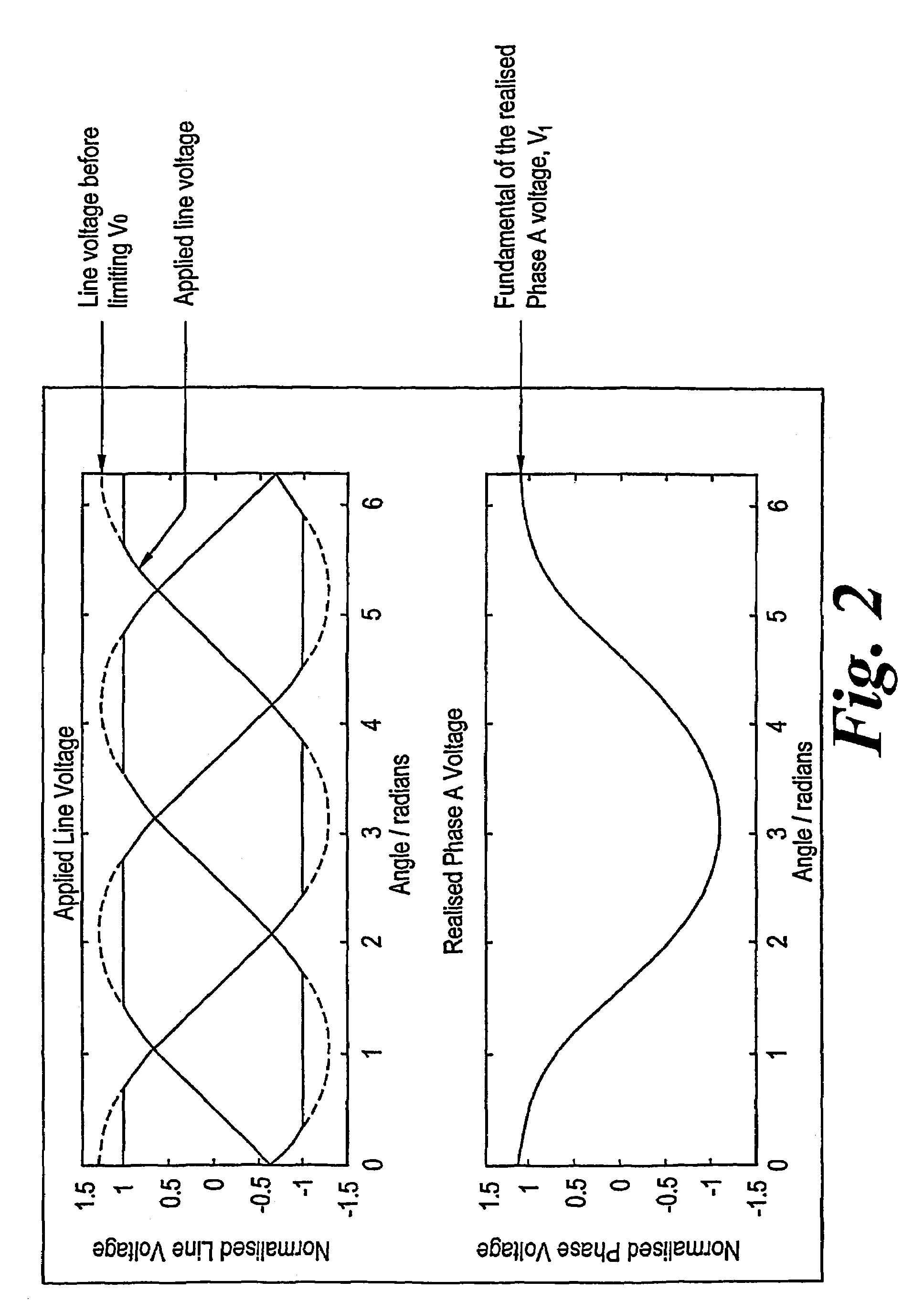
[0004]It is an aim of the invention to maximise the magnitude of the fundamental phase
voltage produced by a single
current sensor drive
system.
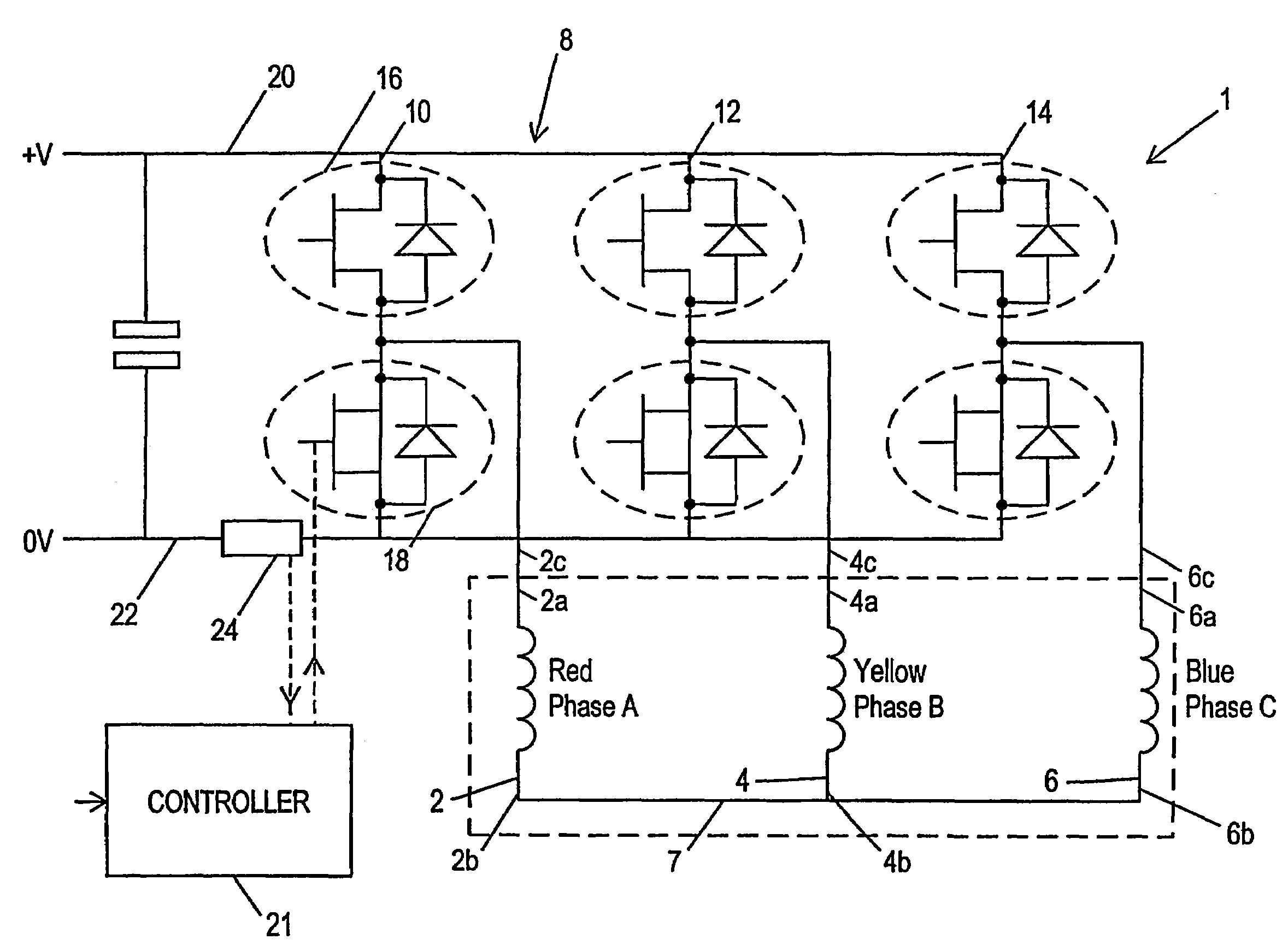
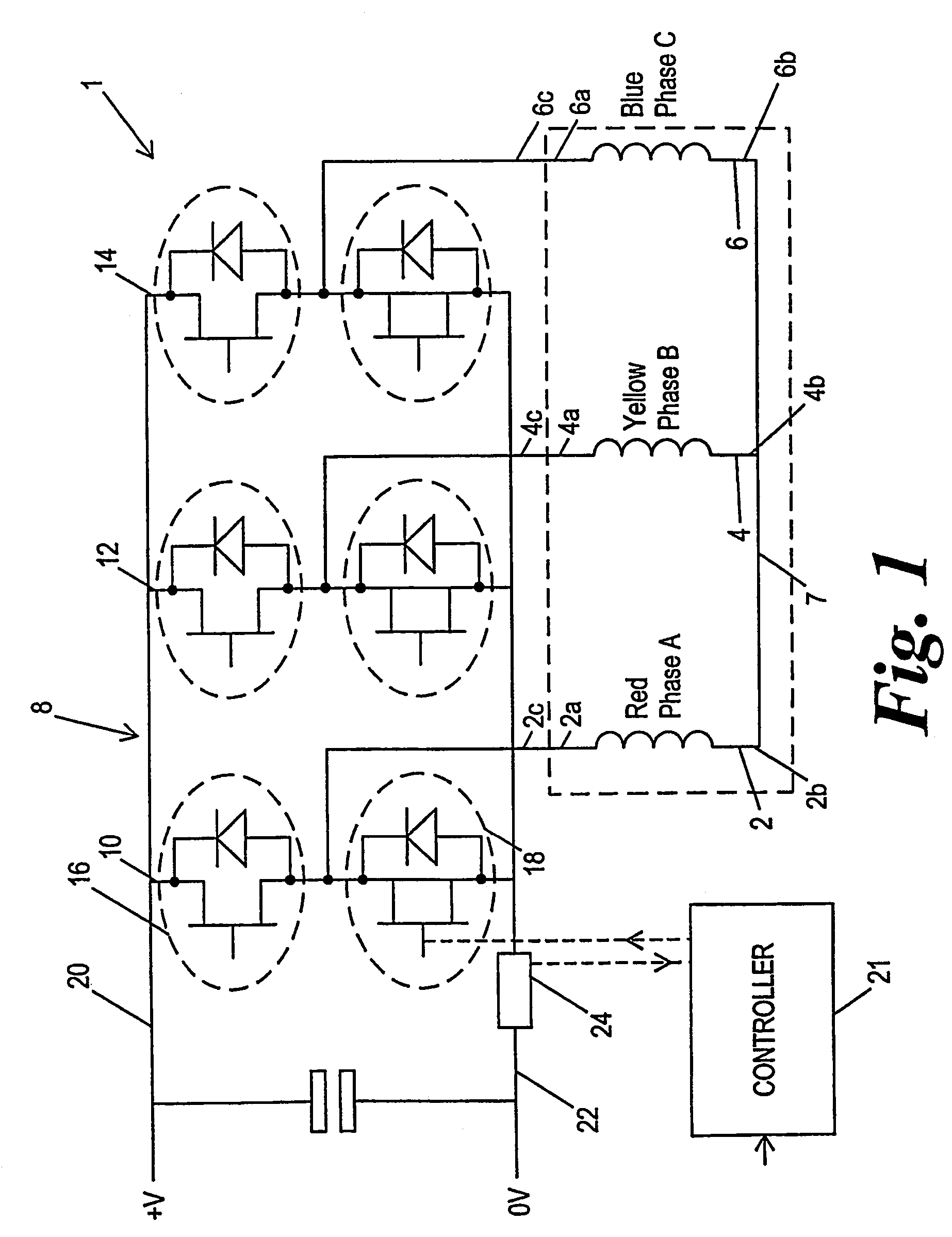
[0006]The present invention further provides a drive system for a multi-phase brushless motor comprising a plurality of phases, the system comprising a drive circuit including switch means for varying the
electric potential applied across each of the windings by switching the drive circuit between a plurality of states, a current sensor connected such that it can sense the instantaneous
total current flowing through the windings, and control means arranged to provide
pulse width modulated drive signals to control the switch means so as to control the time that the drive circuit switches between said states in each of a series of
pulse width modulation periods, wherein there is a
dead time associated with switching each of the phases and the control means is arranged such that, in a period during which the circuit is in a first state for a first state time and two other states for respective shorter state times, a gap left between the two shorter state times of sufficient length to avoid overlap of their associated dead times. This means that, at
high voltage demands, the occurrence of zero-
volt states between the two shorter state times can be avoided.
[0010]The present invention still further provides a drive system for a multi-phase brushless motor comprising a plurality of phases, the system comprising a drive circuit including switch means for varying the
electric potential applied to each of the phases by switching the drive circuit between a plurality of states, a current sensor connected such that it can sense the instantaneous
total current flowing through the windings, and control means arranged to provide
pulse width modulated drive signals to control the switch means so as to control the time that the drive circuit switches between said states in each of a series of
pulse width modulation periods, wherein the control means is arranged to control the switching times of the switch means so that
sufficient time is spent in a sufficient number of active states for the current in each of the phases to be determined by means of the current sensor, and the control means is arranged to inhibit a change, between two adjacent periods, of the order in which the switch means are switched within said periods, when the demanded voltage is low, but to allow such change of order when the demanded voltage is high. This can avoid rapid re-ordering of the states within successive PWM periods which can otherwise produce
noise and vibration in the motor.
[0011]The present invention still further provides a drive system for a multi-phase brushless motor comprising a plurality of phases, the system comprising a drive circuit including switch means for varying the
electric potential applied to each of the phases by switching the drive circuit between a plurality of states, a current sensor connected such that it can sense the instantaneous
total current flowing through the windings, and control means arranged to provide
pulse width modulated drive signals to control the switch means so as to control the time that the drive circuit switches between said states in each of a series of pulse width modulation periods, wherein the control means is arranged to control the switching times of the switch means so that
sufficient time is spent in a sufficient number of active states for the current in each of the phases to be determined by means of the current sensor, and the control means is arranged to switch each phase on at a respective on time and off at a respective
off time and either the on times or the off times are at predetermined times in each period. This can help to reduce the amount of computation required as at least part of the timing is fixed for each period.
[0012]The present invention yet further provides a drive system for a multi-phase brushless motor comprising a plurality of phases, the system comprising a drive circuit including switch means for varying the electric potential applied to each of the phases by switching the drive circuit between a plurality of states, a current sensor connected such that it can sense the instantaneous total current flowing through the windings, and control means arranged to provide pulse width modulated drive signals to control the switch means so as to control the time that the drive circuit switches between said states in each of a series of pulse width modulation periods, wherein the control means is arranged to control the switching times of the switch means so that
sufficient time is spent in a sufficient number of active states for the current in each of the phases to be determined by means of the current sensor, and the control means is arranged to abandon current sensing under some operating conditions so as to allow a greater range of pulse width modulation timings. This can increase the maximum available
power output of the motor.

