Power assisted lift for lubricator assembly

Active Publication Date: 2007-12-18
PAL PLUNGERS
View PDF3 Cites 33 Cited by
  • Summary
  • Abstract
  • Description
  • Claims
  • Application Information

AI Technical Summary

Benefits of technology

[0009]The present invention satisfies the needs and alleviates the problems discussed above. The present invention provides an improved lubricator assembly for receiving a well plunger or other downhole tool. The lubricator assembly includes: a lower portion; an upper riser removably attachable to the lower portion; and a hinge con

Problems solved by technology

Thus, the removal, lifting, alignment, and reattachment of the riser can be very difficult and hazardous and often requires the use of a hoist or other lifting device which must be transported to the well site.
However, ev

Method used


Image

  • Power assisted lift for lubricator assembly
  • Power assisted lift for lubricator assembly
  • Power assisted lift for lubricator assembly

Examples


Embodiment Construction

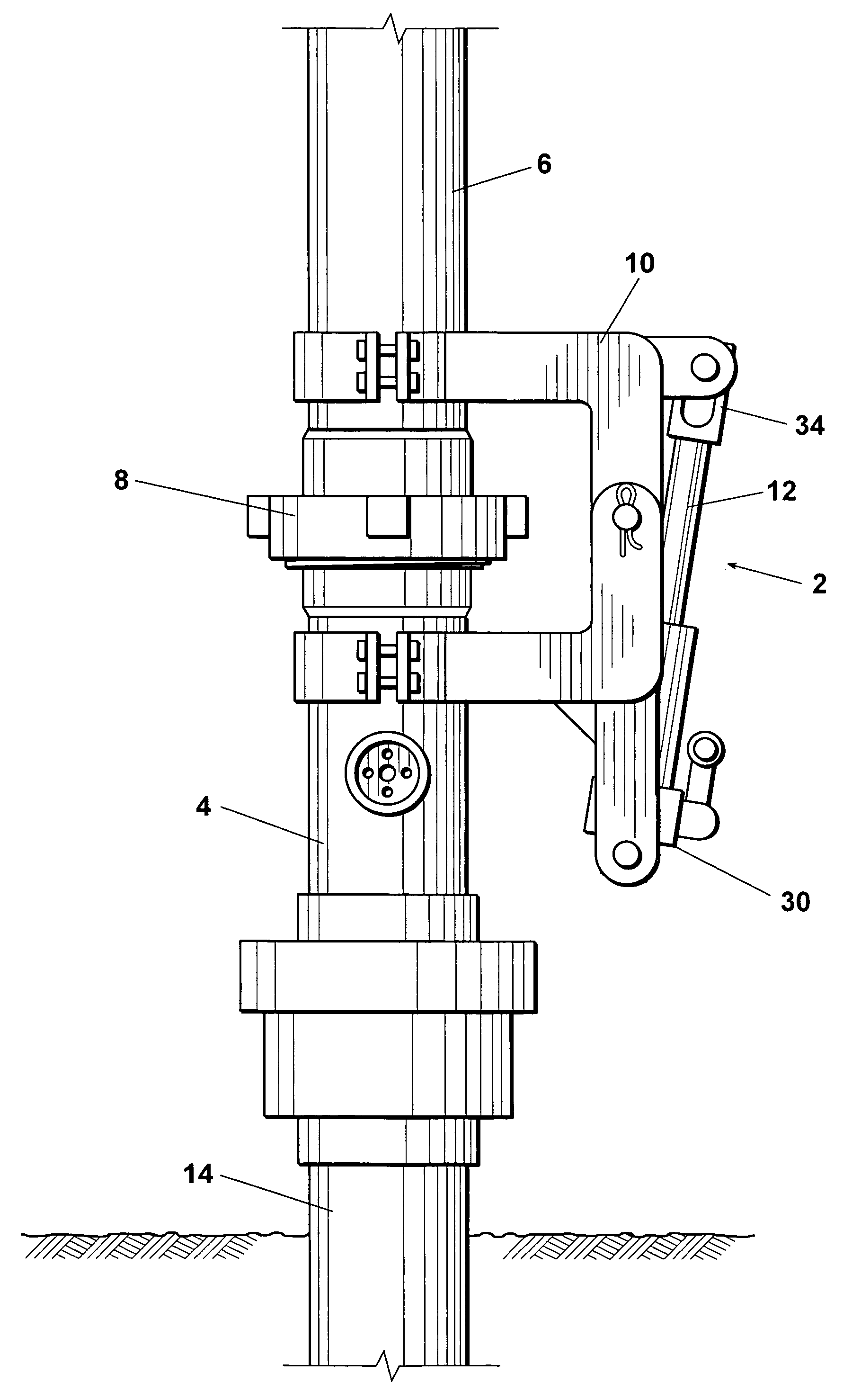
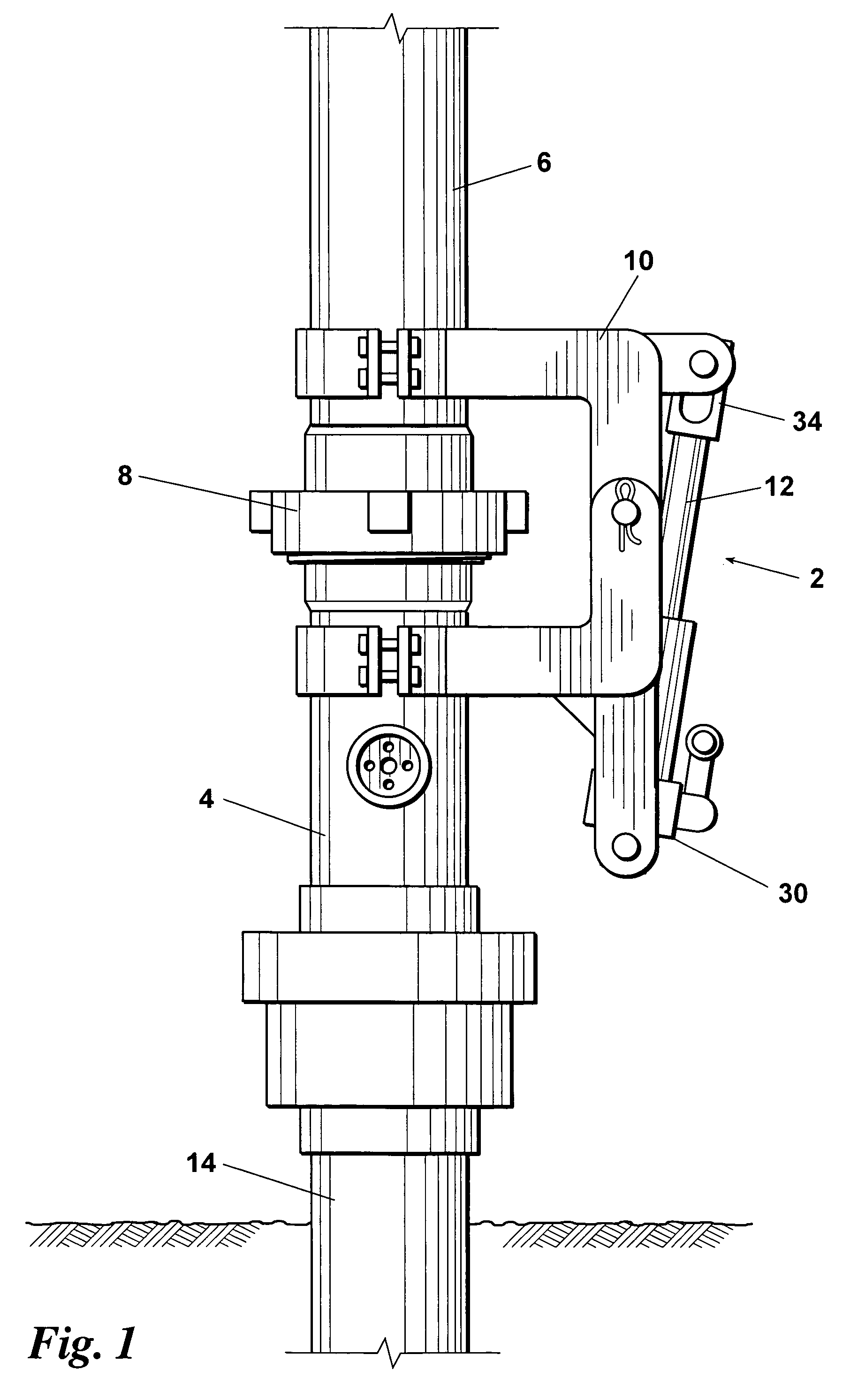
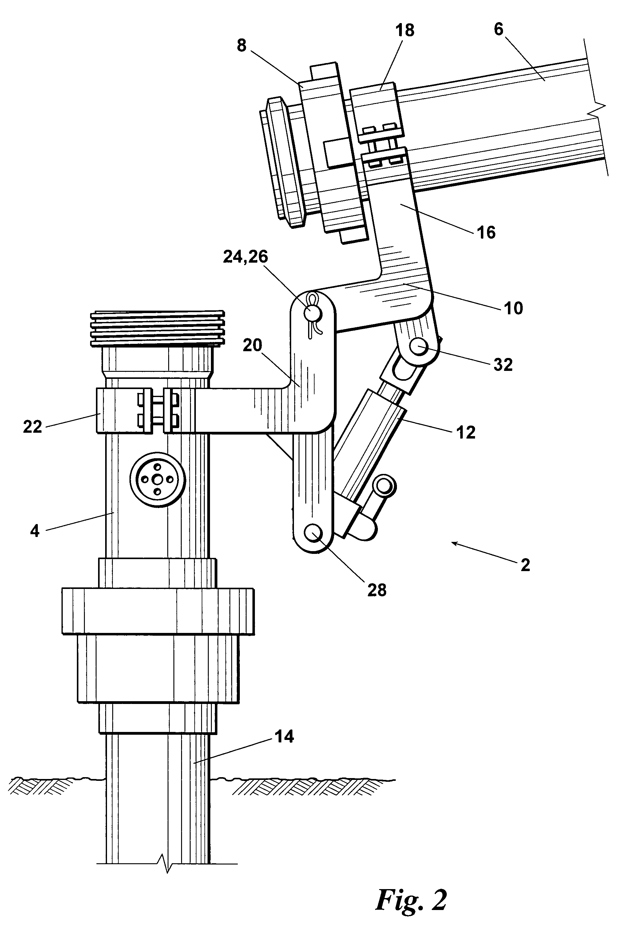
[0013]An embodiment 2 of the inventive lubricator assembly is depicted in FIGS. 1 and 2. As used herein and in the claims, the term “lubricator” refers to any device positionable above ground for receiving a well plunger or other downhole tool. The inventive lubricator 2 comprises: a lower portion 4; an upper riser 6 removably positionable on the upper end of lower portion 4; a threaded coupling 8 or other device for securing upper riser 6 on lower portion 4; a hinge structure 10 connected between upper riser 6 and lower portion 4; and a power lifting device 12 for lifting the upper riser 6 onto and off of the lower portion 4. In embodiment 2, the lower portion 4 is an adapter which is secured on the upper end of a well casing or other tubular 14. However, it will be understood that the lower portion 4 could simply be the upper end of the casing or tubular 14 itself.

[0014]The hinge 10 comprises: a top portion 16 having a bracket assembly 18 for attachment to the upper riser 6; a bot...


PUM


Abstract

An improved lubricator assembly for receiving a well plunger or other downhole tool wherein a hinge is connected between a lower portion and an upper riser of the lubricator assembly and a power lifting device is included for moving the upper riser off of and onto the lower portion of the lubricator assembly.

Description

FIELD OF THE INVENTION[0001]The present invention relates to lubricator assemblies for well plungers and other downhole tools.BACKGROUND OF THE INVENTION[0002]Plungers have been used heretofore for lifting, recovering, and / or removing oil, water, or other fluids from well casings and other tubulars. In some wells, due to relatively low formation pressures and / or other formation conditions, liquids tend to accumulate at some level within the well casing rather than flowing naturally to the surface. Plungers offer potential benefits over conventional pumps, submersible pumps, and other power-operated devices for recovering or removing such fluids.[0003]Various types of plunger devices are known in the art. By way of example, one common type of plunger comprises: an elongate housing assembly; one or more external sealing devices which can be actuated to sealingly contact the interior wall of the well casing; a flow passage extending through the housing assembly; and a valve for opening...

Claims


Application Information

Patent Timeline
IPC IPC(8): E21B19/00
CPCE21B43/121E21B19/06
Inventor MAYFIELD, WINDEL O.MOORE, ROBERT L.
Owner PAL PLUNGERS
Why Eureka
Try Eureka