
Flashlight

a technology for flashing lights and batteries, applied in the field of flashing lights, can solve the problems of not being able to properly reassemble batteries and/or components, affecting the operation of the light as well as the safety of the person, and loosing the lens cap, so as to prevent the use of the flashligh

Active Publication Date: 2007-12-18
ENERGIZER BRANDS
View PDF14 Cites 12 Cited by
  • Summary
  • Abstract
  • Description
  • Claims
  • Application Information

AI Technical Summary

Benefits of technology

[0005]The present invention also relates to a flashlight that is capable of producing different size light patterns. The flashlight includes a tubularly shaped housing, a reflector, a light and a focusing assembly. The housing, which defines an enclosed cavity, has an exterior surface, a first end and a second end. The first end defines an opening having a light transparent material disposed there across. The reflector is secured within the cavity adjacent the opening in the housing's first end. The light is located within the reflector. The focusing assembly includes a circular, rotatable ring disposed around the exterior of the housing. The rotatable ring contacts a carrier and holder subassembly through the housing. The subassembly moves laterally within the housing in response to rotational movement of the rotatable ring. The subassembly causes the light to move laterally within the reflector thereby altering the size of the light patterns produced by the flashlight.

Problems solved by technology

Unfortunately, loosening the lens cap can be detrimental to the operation of the light as well as the safety of the person using the light.
For example, a problem can occur if a consumer accidentally removes the lens cap from the flashlight's housing while trying to adjust the focus of the light.
If the consumer is in a dark location when the focus of the light must be adjusted and the lens cap is unintentionally and unexpectedly separated from the remaining portion of the housing, the user may drop one or more of the light's components and thus not be able to properly reassemble the batteries and / or components thereby precluding further use of the flashlight.
Another problem can occur if the flashlight is used in an environment where the flashlight may be unintentionally sprayed with water such as when the light is used by a firefighter during the act of extinguishing a fire.
If water accumulates in the portion of the flashlight's housing that contains the batteries, switch and light bulb, the flashlight's performance may deteriorate due to rusting of the battery's terminals or the creation of an electrical short circuit in the switch.
Either problem can lead to premature failure of the light.
Yet another problem with flashlights that require the consumer to loosen the lens ring in order to adjust the focus of the light is the tendency of the light not to remain at the focused position for an extended period of time because the lens cap and flashlight housing are loosely secured to one another.

Method used


Image

  • Flashlight
  • Flashlight
  • Flashlight

Examples


Embodiment Construction

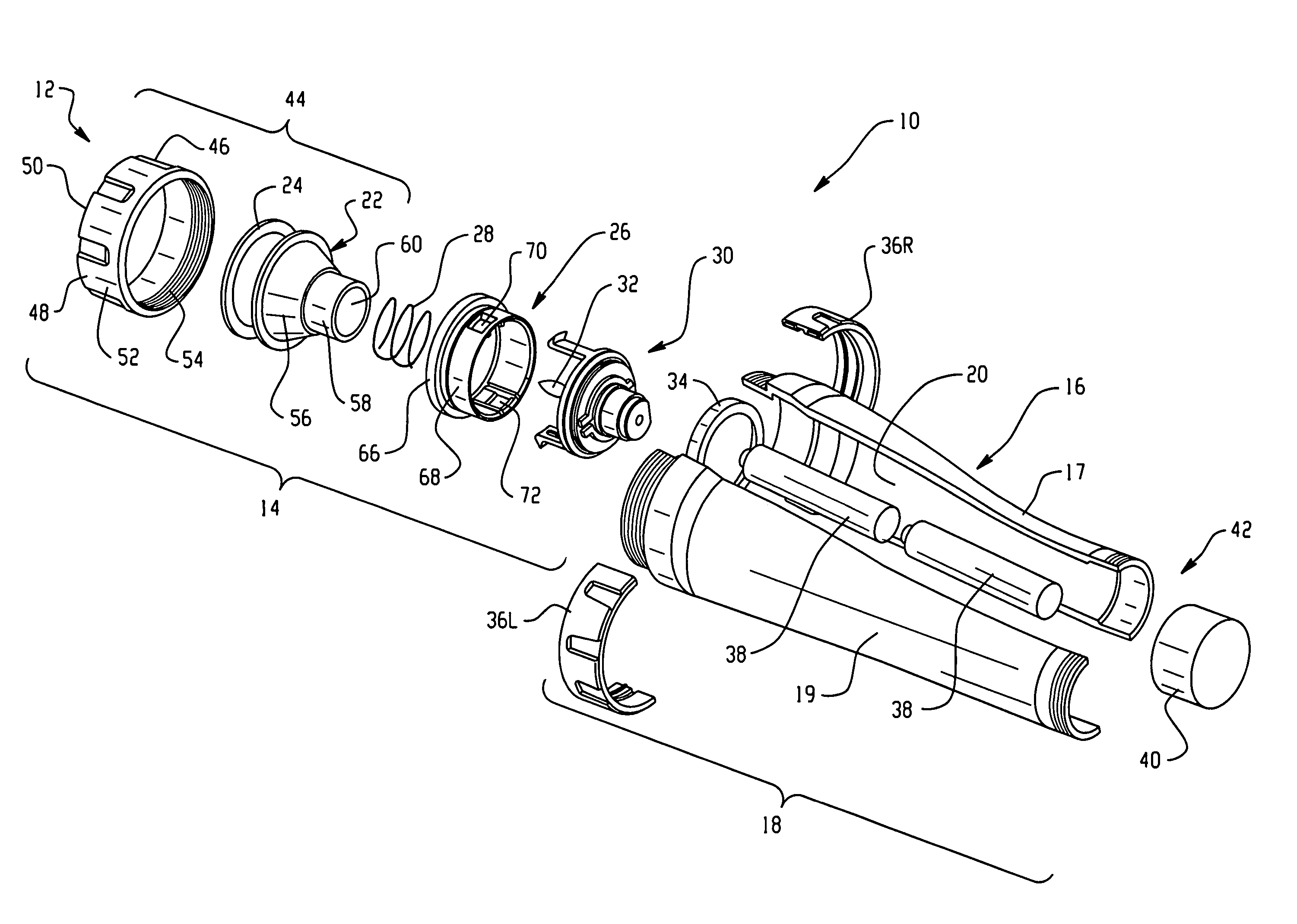
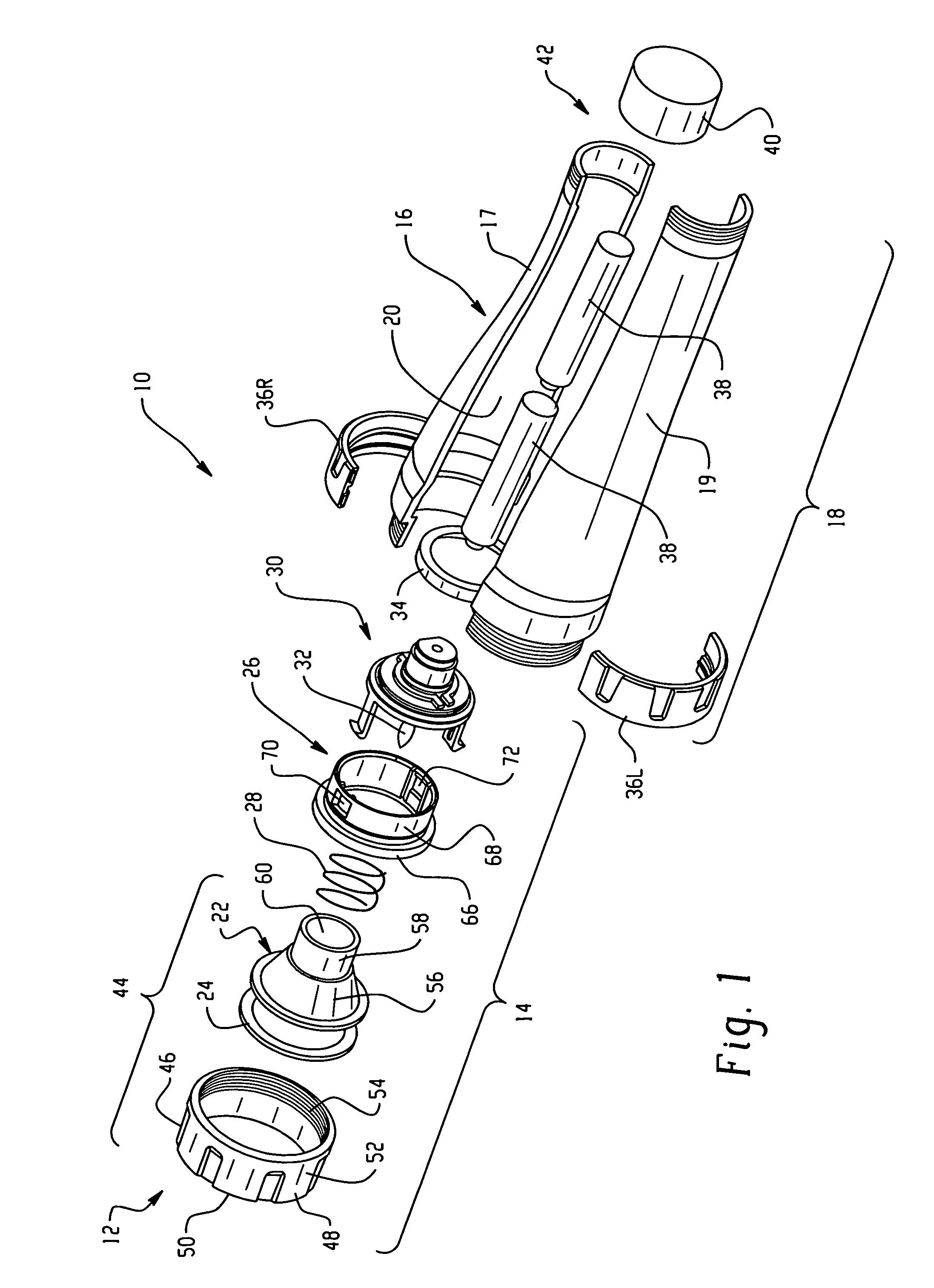
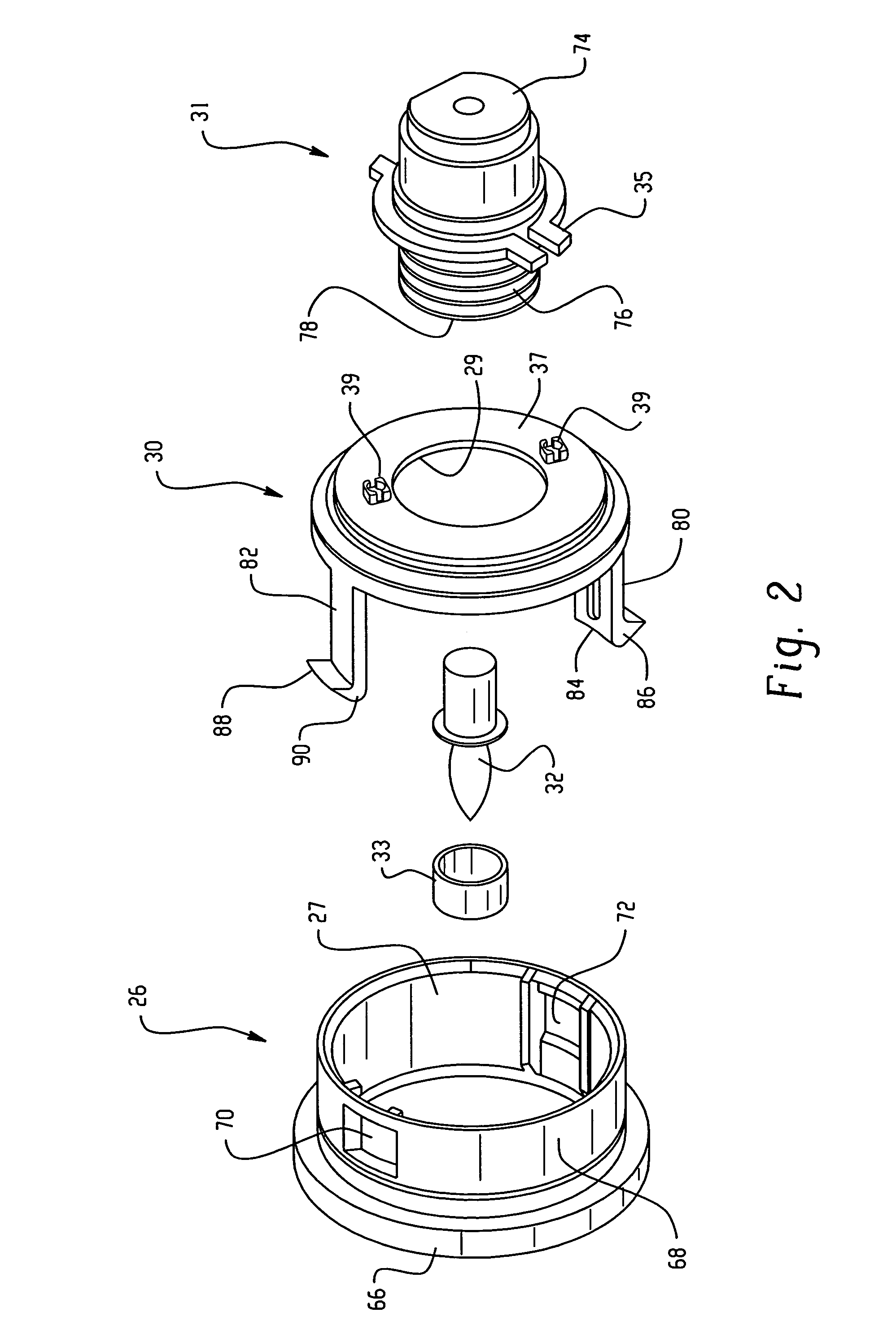
[0014]Shown in FIG. 1 is an exploded perspective view of a portable lighting device 10 of this invention which is referred to herein as a flashlight. In this embodiment, the following components are secured to one another. The lighting device's housing includes the outer surfaces of lens cap 42, body housing 16 and end cap 40. Body housing 16 comprises right side body housing 17 and left side body housing 19. Beginning at a first end 12 of the flashlight is a lens cap assembly which is also identified herein as first section 14. The lens cap assembly is removably secured to second section 18. When first section 14 is secured to second section 18, cavity 20 (see FIG. 7) is defined therein. The location at which the first section is secured to the second section may be referred to herein as a junction. Contained within the cavity is reflector 22. The reflector contacts lens 24, retaining member 26 and coiled spring 28. Light holder carrier 30 movably and removably engages retaining me...


PUM


Abstract

A portable lighting device, such as a flashlight, having a rotatable band disposed around the exterior of the flashlight is disclosed. Rotational movement of the band is converted to lateral movement of the light emitting element within the flashlight. The structural integrity of the flashlight is not compromised when the rotatable band is rotated around the flashlight to adjust the width of the projected pattern of light.

Description

BACKGROUND OF THE INVENTION[0001]This invention generally relates to flashlights. More particularly, this invention is concerned with flashlights that have a focusing mechanism incorporated therein.[0002]Portable lighting devices, such as flashlights and lanterns, are commercially available in a wide array of embodiments. Some embodiments, such as tubularly shaped flashlights, are required to produce a narrow pattern of light that brightly illuminates a small area that must be closely inspected as well as a broad, less intense pattern of light that illuminates a much larger area. Some flashlights include a mechanism that can be used to change the pattern of light from broad to narrow and from narrow to broad as needed and are commonly known as “focusable lights”. Many commercially available focusable lights adjust the size of the projected light beam by rotating the lens cap which is threaded onto one end of the flashlight's housing. The lens cap typically contains the transparent l...

Claims


Application Information

Patent Timeline
Patent Type & Authority Patents(United States)
IPC IPC(8): F21L4/04
CPCF21V14/025F21L4/005
Inventor AU, KANG WOONNG, SIU BONGTANG, WING ON
Owner ENERGIZER BRANDS
Learn More