Shielded electrical connector with improved insulative housing

a technology of shielded electrical connectors and insulative housings, which is applied in the direction of coupling device connections, television systems, and coupling protective earth/shielding arrangements, etc., can solve the problems of signal interference between the terminals, no partitions positioned among the terminal ends to separate them from each other, etc., and achieve the effect of improving the insulative housing

Inactive Publication Date: 2007-12-18
HON HAI PRECISION IND CO LTD
View PDF7 Cites 30 Cited by
  • Summary
  • Abstract
  • Description
  • Claims
  • Application Information

AI Technical Summary

Benefits of technology

[0011]A primary object of the present invention is to provide a shielded electrical connector having an improved insulative housing, wherein a plurality of terminals can be securely retained in the insulative housing.
[0012]Another object of the present invention is to provide a shielded electrical connector having an improved shield for avoiding signal interference among a plurality of terminals mounted thereon.

Problems solved by technology

However, there is no partitions positioned among the ends of the terminals to separate them from each other.
Therefore, the abutting ends are located so closely without any partitions positioned there among that may result in signal interference among the terminals.

Method used


Image

  • Shielded electrical connector with improved insulative housing
  • Shielded electrical connector with improved insulative housing
  • Shielded electrical connector with improved insulative housing

Examples


Embodiment Construction

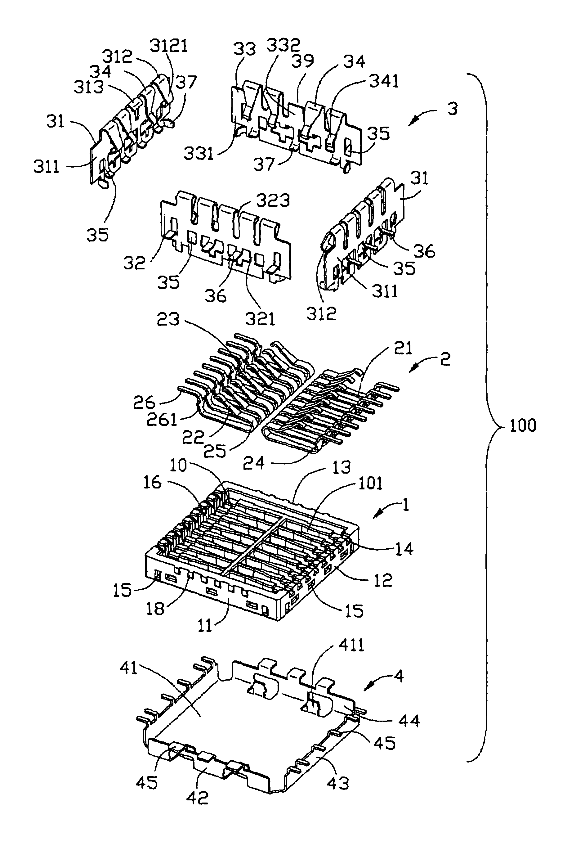
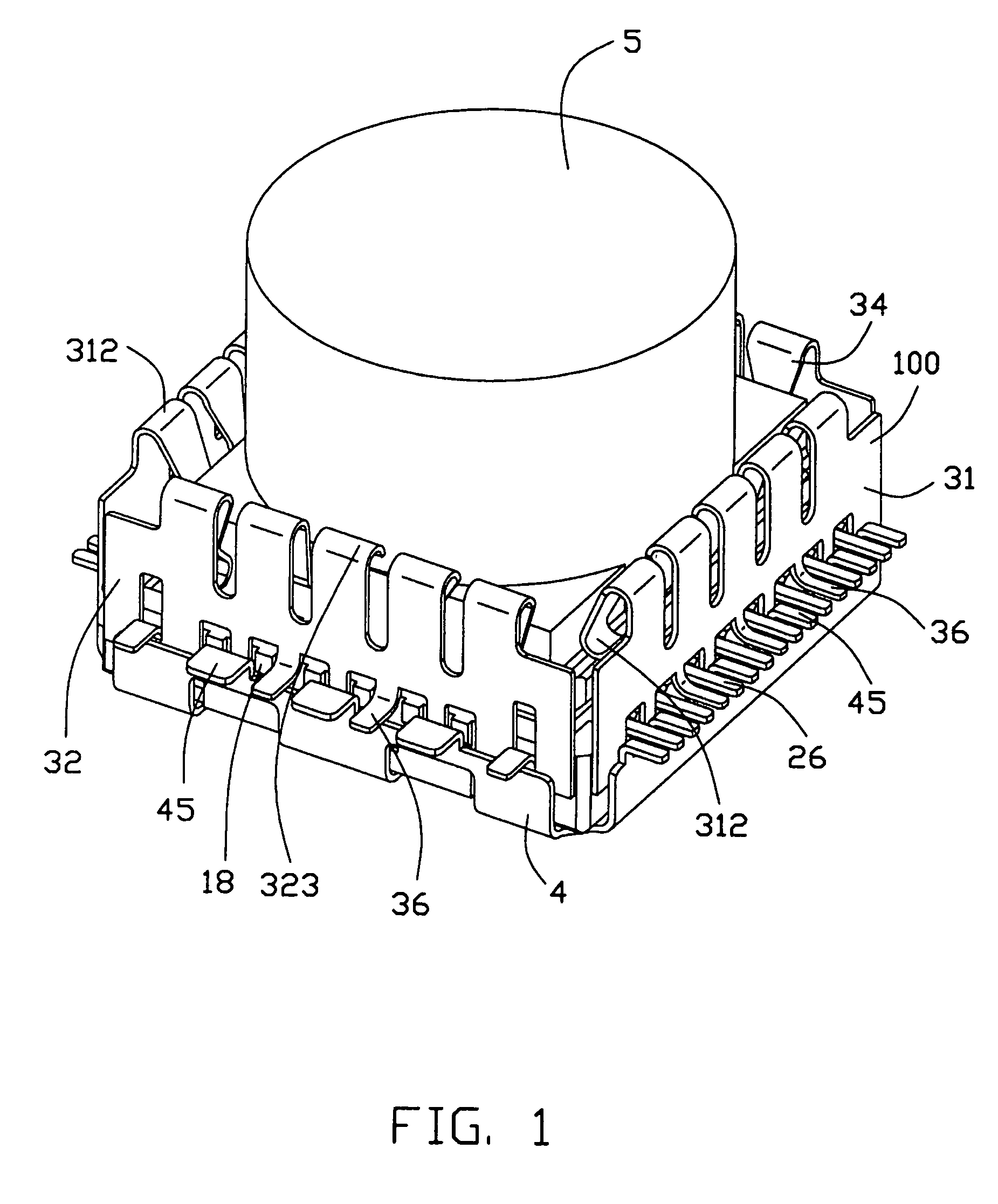
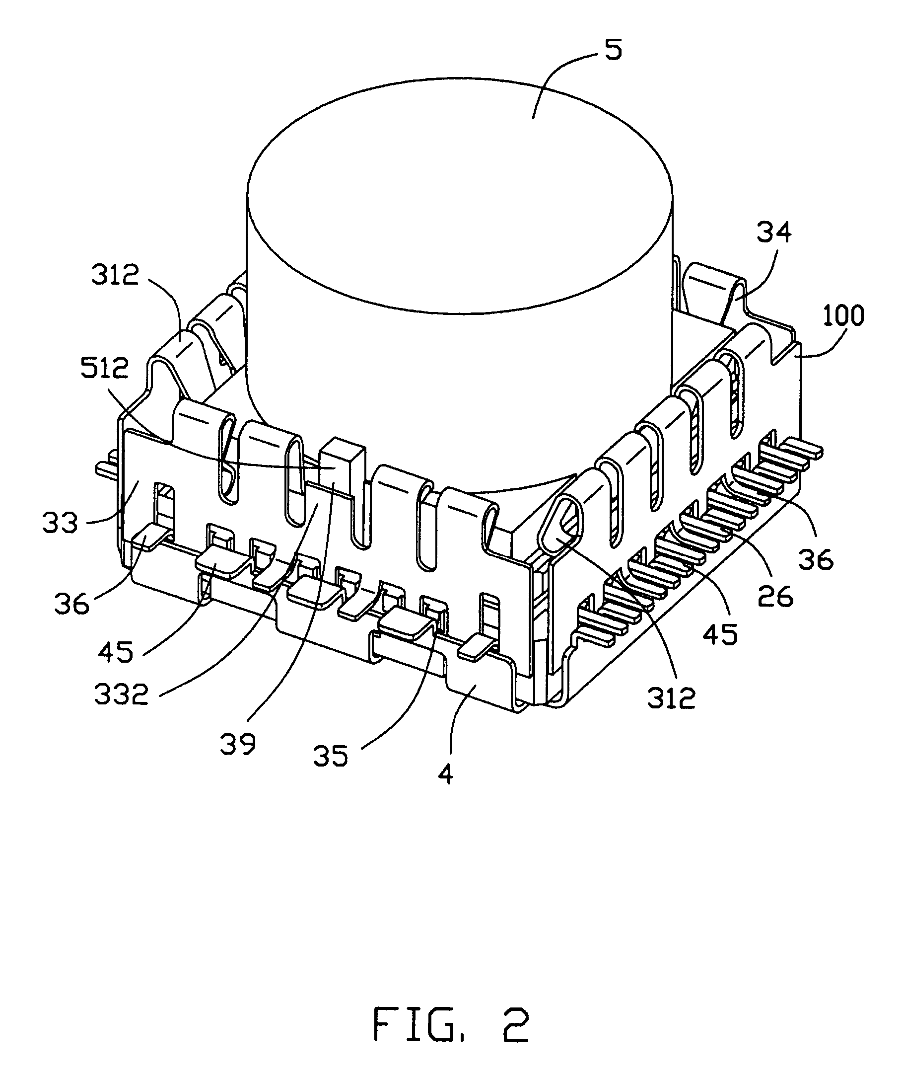
[0023]Reference will now be made to the drawing figures to describe the present invention in detail. Referring to FIG. 1, a shielded electrical connector 100 in accordance with the preferred embodiment of the present invention is adapted for electrically connecting a camera module 5 with a PCB (not shown). In fact, the shielded electrical connector 100 may also be used for other kinds of electrical element in other embodiments.

[0024]Referring to FIG. 4, the shielded electrical connector 100 comprises an insulative housing 1, a plurality of terminals 2 disposed in the insulative housing 1, a side shield 3 mounted around the insultaive housing 1 and a bottom shell 4 attached to a bottom of the insulative housing 1.

[0025]Referring to FIGS. 4-8, The insulative housing 1 is a rectangular board, comprising a bottom board 17, a plurality of walls 11, 12, 13 extending upwardly from the bottom board 17 to thereby define a cavity 10 therebetween. The insulative housing 1 defines therein a plu...


PUM


Abstract

An shielded electrical connector (100), to which an electrical element (5) is electrically connected, includes an insulative housing (1) defining a number of passageways (101), a number of terminals (2) retained in the passageways, a side shield (3) and a bottom shell (4). The insulative housing also has a bottom board (17) defining a number of grooves (170) communicating with the passageways. Each terminal includes a soldering portion (26) and a body portion (21) partially exposed to the groove and straddling over the groove.

Description

CROSS-REFERENCE TO RELATED APPLICATIONS[0001]This patent application is a continuation-in-part of a pending U.S. patent application Ser. No. 11 / 148,503, now U.S. Pat. No. 7,147,481, filed Jun. 08, 2005, and entitled “SHIELDED ELECTRICAL CONNECTOR WITH ANTI-MISMATING MEANS”, which is invented by the same inventor as this patent application and assigned to the same assignee with this application.BACKGROUND OF THE INVENTION[0002]1. Field of the Invention[0003]The present invention relates to a shielded electrical connector in which an electrical element such as a camera module is fitted.[0004]2. Description of Related Art[0005]With development of cellular mobile phones or the likes, a lot of functions such as taking photos are added to the mobile phones or the likes. In order to achieve the functions, an electrical element such as a camera module is furnished to a mobile phone or the likes in virtue of an electrical connector. Generally, a shield member is assembled to the electrical c...

Claims


Application Information

Patent Timeline
Patent Type & Authority Patents(United States)
IPC IPC(8): H01R12/00
CPCH01R13/2442H01R13/65802H01R12/716H04N5/2257H01R2201/16H01R13/6582H04N23/57
Inventor YANG, MENG-HUAN
Owner HON HAI PRECISION IND CO LTD
Why Eureka
Try Eureka