
Elevator system

An elevator system and elevator control technology, applied in signal transmission systems, elevators in buildings, telephone communication, etc., can solve problems such as setting, layout design and construction difficulties, and achieve the effect of utilizing space

Inactive Publication Date: 2009-02-11
TOSHIBA ELEVATOR KK
View PDF3 Cites 20 Cited by
  • Summary
  • Abstract
  • Description
  • Claims
  • Application Information

AI Technical Summary

Problems solved by technology

There are the following problems: with the limited space in the hoistway, various sensors related to the arrival of the car floor (Japanese original: implantation) and the excessive winding of the main rope are required for each equipment in the hoistway, including the door opening and closing detection switch. It is difficult to install, layout, and construct each device, including safety devices such as detection sensors.

Method used


Image

  • Elevator system
  • Elevator system
  • Elevator system

Examples


Embodiment Construction

[0045] Next, various embodiments of the present invention will be described with reference to the drawings.

[0046] (first embodiment)

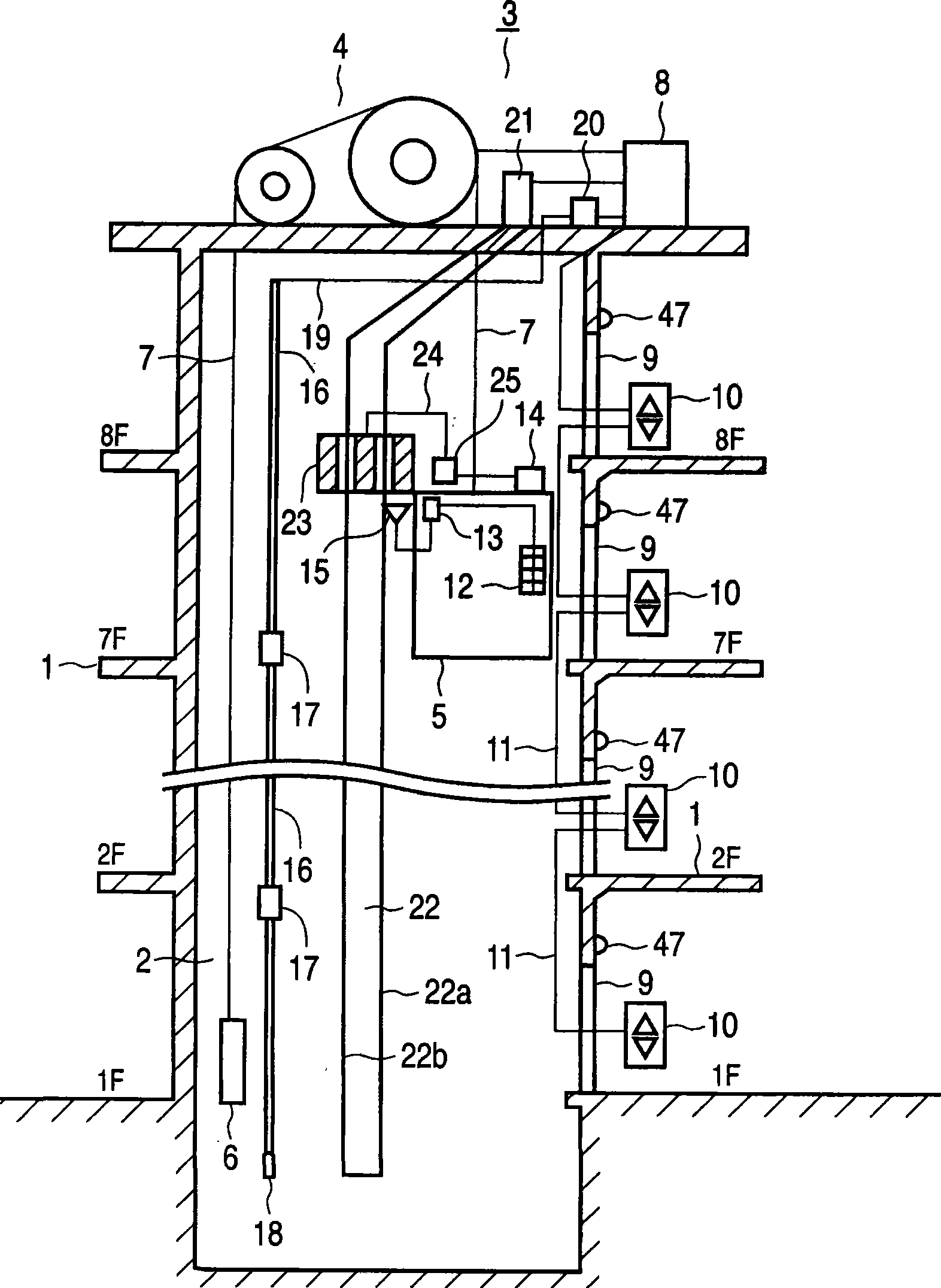
[0047] figure 1 A schematic diagram showing a schematic configuration of an elevator system according to a first embodiment of the present invention.

[0048] A winch 4 is provided in the machine room 3 on the upper side of the elevator shaft 2 that runs through each floor 1 of the building. A main cable 7 is hung on the winch 4 , and one end of the main cable 7 is connected to the car 5 of the elevator, and the other end is connected to the counterweight 6 . The hoist 4 is rotated in response to an instruction from an elevator control unit 8 constituted by a computer, and moves the car 5 to the designated floor 1 . In the elevator lobby of each floor 1, a hall call registration device 10 made of a small computer is installed next to the elevator door 9 . On the upper side of the elevator door 9, a hall signal lamp 47 notifying that the ...


PUM


Abstract

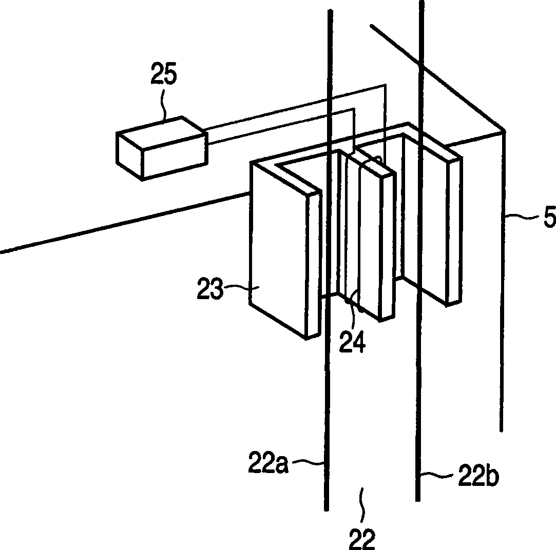
The invention relates to an elevator system, comprising: a cage (5) moving along a guide rail (28) in an elevator shaft (2), power supply devices (22-25) supplying power to the cage in a non-contact mode, an elevator control part (8) moving the cage to the floor designated by lobby calling of each floor (1) and cage calling in the cage (5), and wireless data transmission devices (13, 15, 16, 20) for exchanging various information between the elevator control part and the cage in a wireless mode. Power supply wires (22a, 22b) for supplying power to the cage in a non-contact mode and a leakage coaxial cable (16) for exchanging information with the cage in a wireless mode are blocked on a support (34) of the guide rail for guiding the cage, therefore, the cage (5) in the elevator shaft (2) of the elevator system obtains high-speed stable operation.

Description

technical field [0001] The present invention relates to an elevator system installed in a building, and more particularly to an elevator system in which the wiring arrangement in an elevator shaft on which a car on which an elevator user rides moves up and down is improved. Background technique [0002] In an elevator system installed in a building such as a building, a car on which elevator users ride is arranged in an elevator shaft that passes through each floor of the building. The car is moved up and down by a hoist installed in the machine room on the upper side of the hoistway. More specifically, a car is installed at one end of the main cable wound on the winch, and a counterweight is installed at the other end. [0003] And, when the hall call is input to the hall call registration device installed in the elevator hall of each floor or the car call is input to the car call registration device installed in the car, the elevator control part will drive the hoist to m...

Claims


Application Information

Patent Timeline
Patent Type & Authority Applications(China)
IPC IPC(8): B66B7/00B66B11/02B66B3/00B66B1/00G08C17/02H04M11/00
Inventor 中田好彦中垣薰雄出森公人繁田正昭竹田顺二山本明
Owner TOSHIBA ELEVATOR KK
Learn More