
Display module and display device

A display module and display panel technology, applied to antenna support/installation devices, devices that enable antennas to work in different bands at the same time, static indicators, etc., can solve the problems of thin, light, integrated, and low-cost equipment , to avoid signal interference

Active Publication Date: 2019-08-02
SHANGHAI TIANMA MICRO ELECTRONICS CO LTD
View PDF8 Cites 22 Cited by
  • Summary
  • Abstract
  • Description
  • Claims
  • Application Information

AI Technical Summary

Problems solved by technology

[0005] In view of this, the present invention provides a display module and a display device to solve the problem that existing equipment is difficult to develop in the direction of lightness, lightness, integration, and low cost.

Method used


Image

  • Display module and display device
  • Display module and display device
  • Display module and display device

Examples


Embodiment Construction

[0034] Various exemplary embodiments of the present invention will now be described in detail with reference to the accompanying drawings. It should be noted that the relative arrangements of components and steps, numerical expressions and numerical values ​​set forth in these embodiments do not limit the scope of the present invention unless specifically stated otherwise.

[0035] The following description of at least one exemplary embodiment is merely illustrative in nature and in no way taken as limiting the invention, its application or uses.

[0036] Techniques, methods and devices known to those of ordinary skill in the relevant art may not be discussed in detail, but where appropriate, such techniques, methods and devices should be considered part of the description.

[0037] In all examples shown and discussed herein, any specific values ​​should be construed as exemplary only, and not as limitations. Therefore, other instances of the exemplary embodiment may have dif...


PUM


Abstract

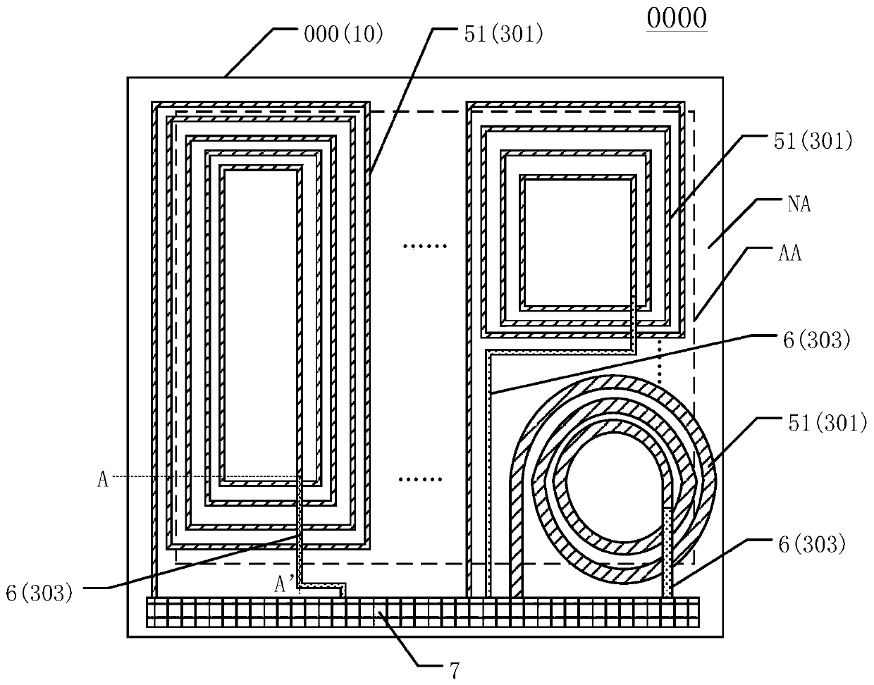
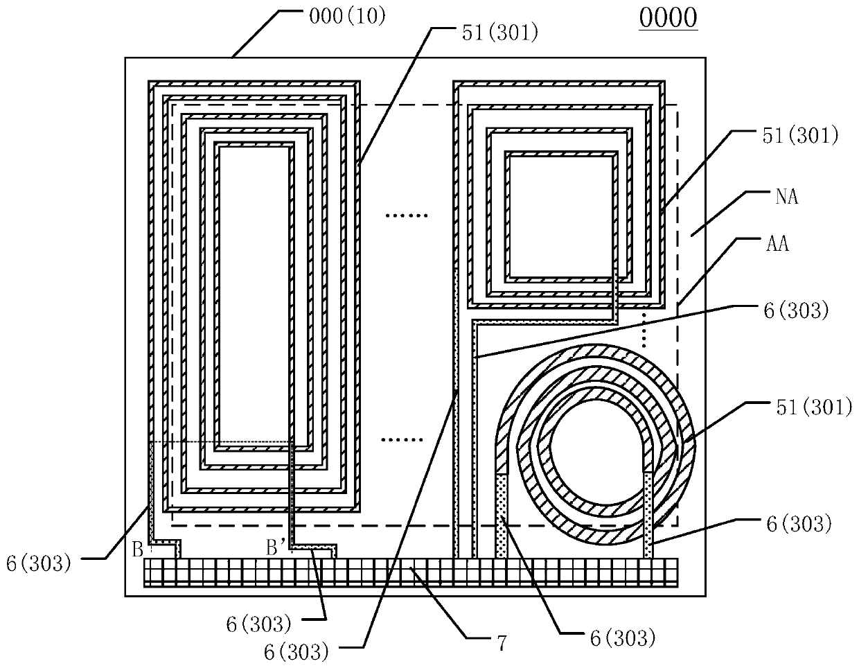
The invention discloses a display module and a display device, and belongs to the technical field of display, the display module comprises a display panel, and the display panel comprises a first substrate, a thin film transistor array layer, a second substrate and a coil film layer; wherein the coil film layer at least comprises a first metal layer, a first insulating layer, a second metal layerand a second insulating layer, the first metal layer comprises at least one first coil, the second metal layer comprises at least one signal line, and one first coil of the first metal layer is electrically connected with one or two signal lines of the second metal layer; the orthographic projection of the first coil to the first substrate is at least partially located within the display area range. The display device comprises the display module. The coil film layer is arranged in the display panel, and wireless transmission with multiple functions can be integrated on one panel, so that thecost is reduced, the integration level is improved, and equipment is further developed to be light, thin and integrated.

Description

technical field [0001] The present invention relates to the field of display technology, and more specifically, to a display module and a display device. Background technique [0002] The existing wireless transmission functions integrated in mobile phones, POS machines and other equipment are all realized by integrating electromagnetic coils in the whole machine. In essence, they all use the principle of electromagnetic induction to input alternating current into the sending coil, and the sending coil generates alternating current. This changing magnetic field will generate an alternating current in the receiving coil, realizing the transmission of electrical energy or signals from the sending coil to the receiving coil. [0003] However, with the development of science and technology, the functions of modern electronic communication equipment are becoming more and more powerful. Taking mobile phones as an example, it integrates many functions such as calling, surfing the I...

Claims


Application Information

Patent Timeline
Patent Type & Authority Applications(China)
IPC IPC(8): G02F1/1362G02F1/1368G02F1/133G02F1/167G02F1/1675G02F1/16755G02F1/1685
CPCG02F1/136286G02F1/1368G02F1/1362G02F1/13306G02F1/16755G02F1/167G02F1/1685G02F1/1675H01L27/1255H01L27/124G02F1/13338H01Q1/38H01Q7/00H01Q1/22H01Q1/44H01Q1/2291H01Q21/08H01Q5/307H04M1/0266H05K1/189H05K2201/10136
Inventor 林柏全席克瑞欧阳珺婷毛琼琴秦锋孔祥建刘金娥李小和
Owner SHANGHAI TIANMA MICRO ELECTRONICS CO LTD
Learn More