Wireless communication module

a communication module and wireless technology, applied in the direction of coupling device details, coupling device connection, transmission, etc., can solve the problems of not being designed for surface installation on computer or other circuit boards, existing wireless connectivity devices are not generally suitable for oem manufacturers, and ethernet converters did not provide wireless connectivity. , to achieve the effect of simplifying electronics

Inactive Publication Date: 2007-12-18
LANTRONIX
View PDF8 Cites 44 Cited by
  • Summary
  • Abstract
  • Description
  • Claims
  • Application Information

AI Technical Summary

Benefits of technology

[0012]The novel modules can be used wherever a device designer wants a plug-in (or “drop-in”) system that obviates the need for independent design, development and maintenance of wireless capability. Examples include servers, desktop and laptop computers, and even devices such as kitchen appliances with relatively simpler electronics. It is especially contemplated that the novel modules can be used on devices having one or more rigid or flexible component boards, and can be implemented with more than one such module on a given board to provide redundancy, or to provide intra- or inter-board communication.

Problems solved by technology

The earliest Ethernet converters did not provide wireless connectivity.
Subsequent converters, including PCMCIA cards and USB dongles, do provide wireless connectivity, but such devices are not designed for surface installation on computer or other circuit boards.
In addition, the existing converters are designed for particular translations of one protocol to another or they have limited or non-existing MILARRS and other functionality.
Existing wireless connectivity devices are therefore not generally suitable to OEM manufacturers for use in their products.

Method used


Image

  • Wireless communication module
  • Wireless communication module
  • Wireless communication module

Examples


Embodiment Construction

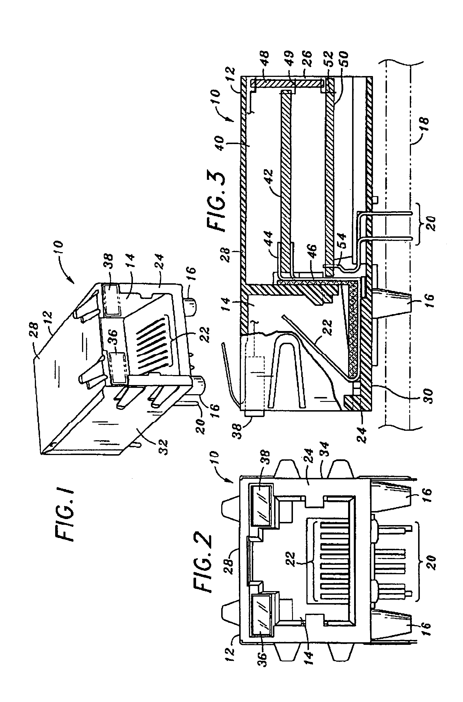
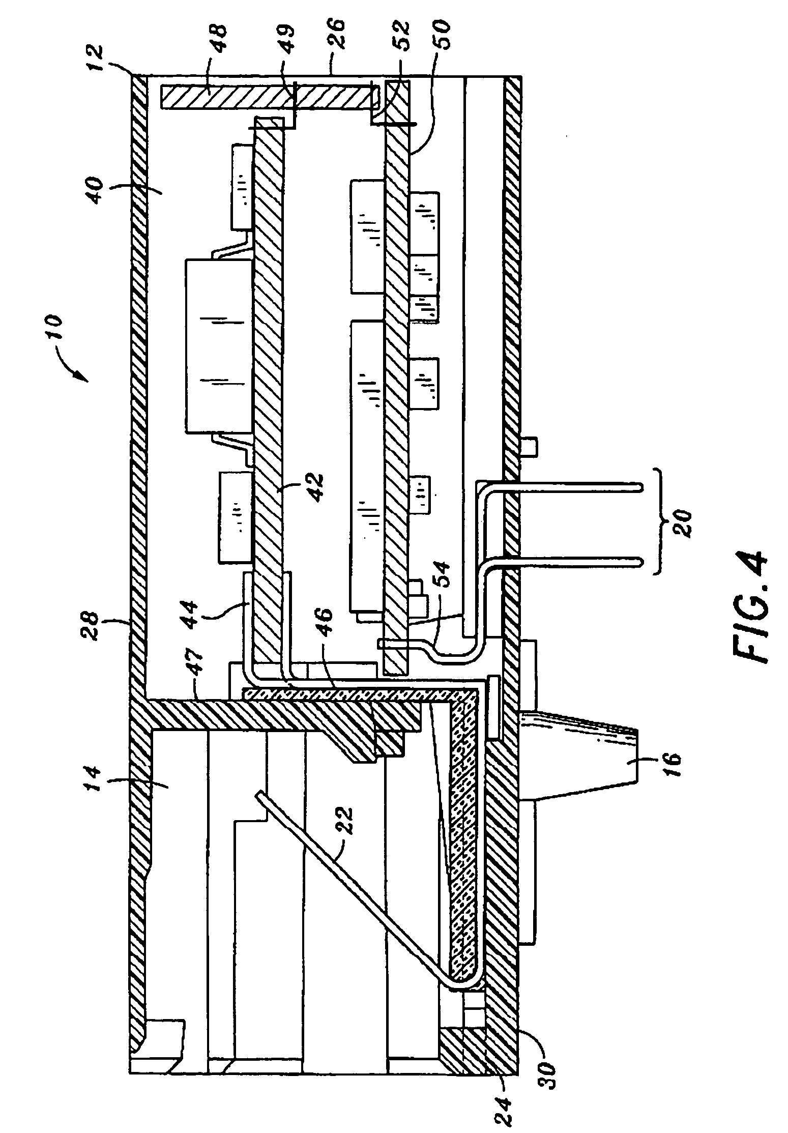
[0028]In FIGS. 1, 2 and 3, module 10 comprises a generally rectangular housing 12. The front of the housing includes an open cavity 14. A metal Faraday shield covers the top, sides and back of the housing and provides for electromagnetic-radiation (EMR) protection. The module 10 additionally includes spring biased grounding tabs 16 that connect the Faraday shield to chassis (earth) ground by contacting the enclosure in which the connector is mounted. Also shown is an array of leads 20 for electrically interconnecting the module 10 to a printed circuit board (PCB) 18.

[0029]The cavity 14 of the housing 12 incorporates a planar array of parallel electrical contacts 22 to provide the necessary electrical contacts to form a connector port within the cavity 14. The cavity 14 is sized and dimensioned and the contacts 22 are placed within the cavity to compliment a mating plug (not shown). The sized cavity 14 along with the contacts 22 form a standard RJ-45 connector jack. The jack contacts...


PUM


Abstract

A PCB mountable module includes logic circuitry that translates between serial and wireless communication protocols. Supported standards include I2C, CAN, ProfiBus, SPI, and USB, IP, ARP, UDP, TCP, ICMP, Telnet, TFTP, AutoIP, DHCP, HTTP, and SNMP. Modules can optionally provide security, MILARRS functionality, and web related services such as email alert. The novel modules can be used wherever a device designer wants a plug-in (or “drop-in”) system that obviates the need for independent development and maintenance of wireless capability. Examples include servers, desktop and laptop computers, and even devices such as kitchen appliances with relatively simpler electronics.

Description

CROSS-REFERENCE TO RELATED APPLICATIONS[0001]This application is a continuation-in-part of Ser. No. 11 / 060,664 filed Feb. 17, 2005 now U.S Pat No. 7,018,242, which is a continuation of Ser. No. 10 / 122,867 filed Apr. 15, 2002 now U.S Pat No. 6,881,096.FIELD OF THE INVENTION[0002]The field of the invention is wireless adapters.BACKGROUND OF THE INVENTION[0003]Several serial to Ethernet converters are known, including for example the X-Port™ from Lantronix™, aspects of which were described in the Ser. No. 10 / 122,867 application filed April 2002. This and all other patents and patent applications cited herein are incorporated by reference in their entirety. A more recent example includes the CP / COM™ converter available from Arc Electronics™. (www.arcelect.com).[0004]The earliest Ethernet converters did not provide wireless connectivity. Subsequent converters, including PCMCIA cards and USB dongles, do provide wireless connectivity, but such devices are not designed for surface installat...

Claims


Application Information

Patent Timeline
Patent Type & Authority Patents(United States)
IPC IPC(8): H01R24/00H01R13/66H05K1/14
CPCH04L67/02H04L69/08H01R13/6658H01R13/6691H01R2201/04H01R24/64H05K1/144H04L69/18
Inventor BROWER, CHARLES J.BROWN, CURTIS D.MILLER, DARYL R.
Owner LANTRONIX
Why Eureka
Try Eureka