Valve assembly

a valve assembly and valve body technology, applied in the field of valve assembly, can solve problems such as air or vapor lock, and achieve the effect of convenient maintenance and greater flexibility

Inactive Publication Date: 2007-12-25
GT INVESTMENTS BVI
View PDF15 Cites 5 Cited by
  • Summary
  • Abstract
  • Description
  • Claims
  • Application Information

AI Technical Summary

Benefits of technology

[0007]It is an object of this invention to provide a valve assembly that counteracts the formation of a vapor lock as fluid is drawn into an air-containing chamber.
[0010]It is a further object of this invention to provide a valve assembly that allows greater flexibility in the location of liquid holding tanks in an extraction cleaner.
[0011]It is a further object of the invention to provide a valve assembly that is reliable, and may be easily maintained.

Problems solved by technology

The problem of an air or vapor lock occurs at start up, when liquid is drawn into a chamber containing air.

Method used


Image

  • Valve assembly
  • Valve assembly
  • Valve assembly

Examples


Embodiment Construction

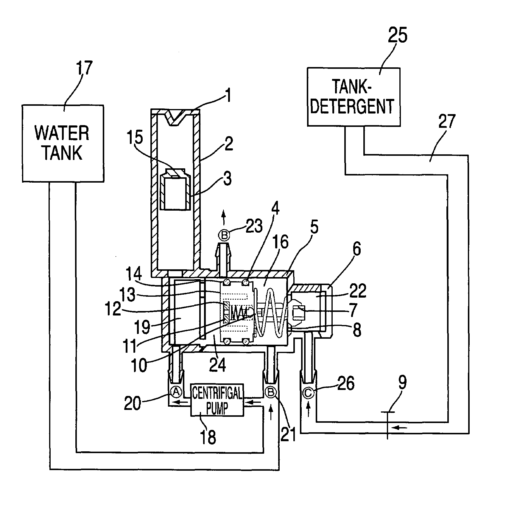
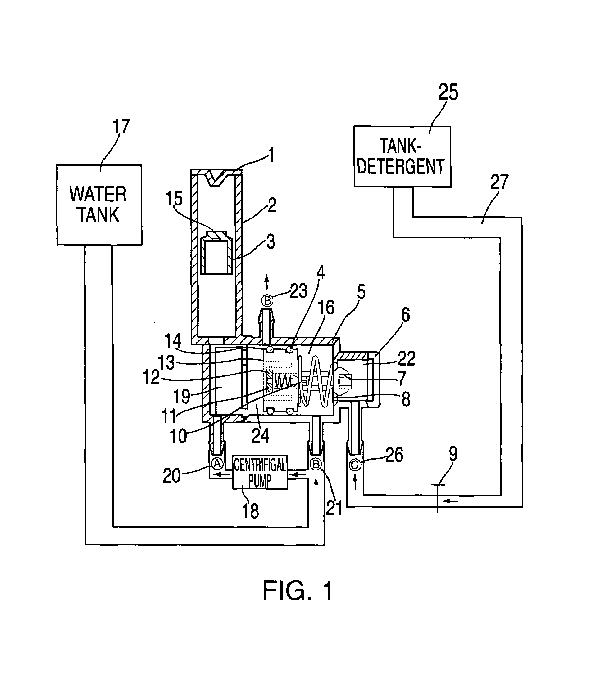
[0017]FIG. 1 shows a preferred embodiment of the valve assembly of the present invention with the valve assembly in the relaxed position. The valve assembly encompasses a number of constituent parts, including a cap-bleeder (1); a bleeder tube body (2); a float-bleeder (3); a first actuator O-ring (4); a shut-off valve body (5); a shut-off valve cover (6); an O-ring (7); a spring (8); a detergent valve (9); a valve (10); a valve cover (11); a second spring (12); a shut-off plunger rod, also denominated as an actuator; (13); a second actuator O-ring (14); a shut-off plunger assembly (15).

[0018]A mixing chamber (16) as shown in FIG. 1 is an exemplar of mixing chambers of the type commonly used in extraction-type cleaners. However, other configurations, shapes, volumes or sizes may be employed without departing from the teachings of the present invention.

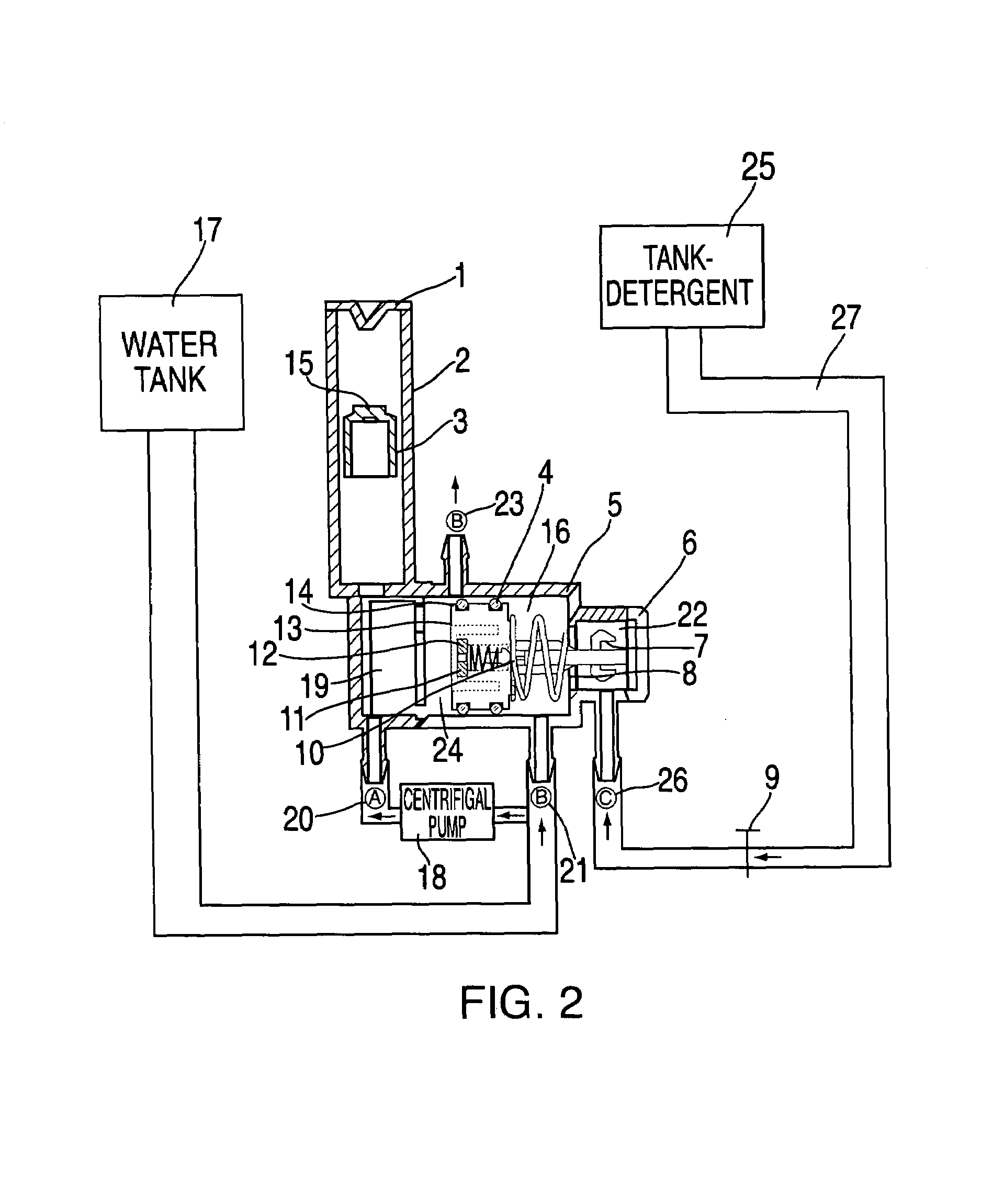
[0019]The positioning of the certain elements affects the performance of the preferred embodiment as follows. Referring to FIG. 1, th...


PUM


Abstract

The invention relates to a valve assembly for use in connection with carpet cleaning extraction machines and similar extraction cleaning devices. The invention allows the intake of liquid and the mixing of different liquids in a mixing chamber, such as clean water with detergent, and the discharge of a selected liquid without the formation of an air or vapor lock that would inhibit the discharge of the selected liquid. In particular, the invention prevents the formation of a vapor lock when water is being drawn into a chamber that would prevent the subsequent discharge or spraying of the liquid.

Description

BACKGROUND OF THE INVENTION[0001]The invention relates to a valve assembly for use in connection with carpet cleaning extraction machines. The invention allows the mixing of different liquids in a mixing chamber, such as clean water with detergent, and the discharge of a selected liquid without the formation of a vapor lock that would inhibit the discharge of the selected liquid. In particular, the invention prevents the formation of a vapor lock when water is being drawn into a chamber that would prevent the subsequent discharge or spraying of either water or a water / detergent mixture.[0002]Carpet cleaning machines of the extraction type are typically used to inject water or a water / detergent mixture into the carpet fibers to be cleaned. The machine then typically extracts the soiled water / detergent mixture by vacuuming, thereby extracting particulate matter and other soiling agents and contaminants from the carpet along with the water and detergent. Examples of such carpet cleanin...

Claims


Application Information

Patent Timeline
Patent Type & Authority Patents(United States)
IPC IPC(8): A47L7/00F16K11/00A47L11/34F16K24/06
CPCA47L11/34F16K24/06A47L11/4083Y10T137/3099
Inventor SHAM, JOHN C. K.
Owner GT INVESTMENTS BVI
Why Eureka
Try Eureka