Wheel assembly for irrigation system

a technology of irrigation system and wheel assembly, which is applied in the field of agricultural irrigation system, can solve the problems of increasing the load on the existing drive motor and gearbox, premature failure of the unit, and affecting the operation of the unit, so as to increase the ground-engaging surface area or “footprint”

Active Publication Date: 2007-12-25
LINDSAY CORP
View PDF12 Cites 27 Cited by
  • Summary
  • Abstract
  • Description
  • Claims
  • Application Information

AI Technical Summary

Benefits of technology

[0003]It would be desirable in some instances to increase the ground-engaging surface area or “foot print” of each wheel assembly, such as where the wheel assemblies are steerable. However, providing larger tires or attaching special enlarged traction structures to the existing wheels necessarily increases the load on their existing drive motors and gearboxes, which can cause the units to malfunction or fail prematurely.

Problems solved by technology

However, providing larger tires or attaching special enlarged traction structures to the existing wheels necessarily increases the load on their existing drive motors and gearboxes, which can cause the units to malfunction or fail prematurely.

Method used


Image

  • Wheel assembly for irrigation system
  • Wheel assembly for irrigation system
  • Wheel assembly for irrigation system

Examples


Embodiment Construction

[0009]The present invention is susceptible of embodiment in many different forms. While the drawings illustrate and the specification describes certain preferred embodiments of the invention, it is to be understood that such disclosure is by way of example only. There is no intent to limit the principles of the present invention to the particular disclosed embodiments.

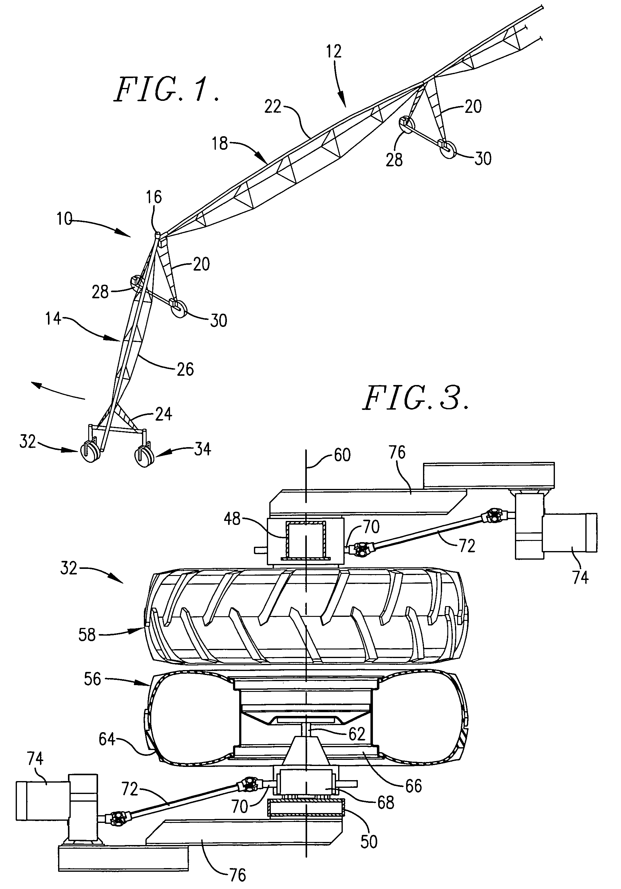
[0010]Although the principles of the present invention have utility with respect to a variety of irrigation systems, they are particularly beneficial when applied to systems wherein at least certain of the wheel assemblies are steerable. For example, steerable wheels are typically used on the auxiliary corner span of a center pivot system wherein the corner span is steered into difficult-to-reach corners of the field as the main span sweeps in a circular path around the primary portion of the field. One such system is disclosed in U.S. Pat. No. 5,695,129 owned by the assignee of the present invention and hereby incorpo...


PUM


Abstract

Mobile towers of an irrigation system have drive wheel assemblies that propel the towers along the ground. At least certain of the wheel assemblies may comprise dual wheels that share a common axis of rotation but are separately driven by their own drive motor. By driving the two separate wheels in unison but with their own individual drive shafts, increased ground-engaging surface area can be obtained without a consequential increase in load for any one motor.

Description

TECHNICAL FIELD[0001]This invention relates to the field of agricultural irrigation systems and, more particularly, to an improved drive wheel assembly for the mobile towers of such systems.BACKGROUND AND SUMMARY[0002]It is known in the art to provide the mobile, water conduit-supporting towers of irrigation systems with drive wheels that propel the towers over ground to be irrigated. Typically, such towers include at least a pair of wheel assemblies at the base of the tower, each assembly comprising a single drive wheel powered by an electric or hydraulic motor.[0003]It would be desirable in some instances to increase the ground-engaging surface area or “foot print” of each wheel assembly, such as where the wheel assemblies are steerable. However, providing larger tires or attaching special enlarged traction structures to the existing wheels necessarily increases the load on their existing drive motors and gearboxes, which can cause the units to malfunction or fail prematurely.[000...

Claims


Application Information

Patent Timeline
Patent Type & Authority Patents(United States)
IPC IPC(8): B05B3/00B05B3/18B60K17/34
CPCA01G25/092
Inventor KORUS, THOMAS J.
Owner LINDSAY CORP
Why Eureka
Try Eureka