Anatomically conforming intraoral dental radiographic sensor

a radiographic sensor and anatomically conforming technology, applied in the field of intraoral sensor design, can solve the problems of image distortion of the intended subject, patient discomfort, and even greater patient discomfort of the sensor, and achieve the effect of increasing patient comfor

Inactive Publication Date: 2007-12-25
CYBER MEDICAL IMAGING INC
View PDF23 Cites 13 Cited by
  • Summary
  • Abstract
  • Description
  • Claims
  • Application Information

AI Technical Summary

Benefits of technology

[0007]Accordingly, an object of the present invention is to provide a configuration for a radiographic sensor that allows for increased patient comfort.
[0008]Another object of the present invention is to provide a configuration for a radiographic sensor that allows for improved coverage of the radiographic subject.
[0009]Yet another object of the present invention is to provide for the incorporation of fiduciary elements within a radiographic sensor that allows for the measurement of the magnitude of image distortion produced when the imaging x-ray beam is not perpendicular to the sensor surface.

Problems solved by technology

However, a common complaint and problem during radiographic exams is patient discomfort during the placement of radiographic sensors within the mouth.
This problem is primarily due to the limited space available for proper placement of the sensors within these regions.
This has been a problem since the inception of dental radiography using standard x-ray film technology.
However this bending contributes to the problems of image distortion of the intended subject as described below.
The patient discomfort problem for these sensors is even greater because these devices are rigid by nature and cannot be bent like film.
With these rigid sensors, the only recourse is to place the sensor at a more comfortable angle and position for the patient, but such positioning is normally not optimal for a diagnostic radiograph of the intended subject.
One study has shown that using such rigid devices results in more sensor placement errors than conventional film, thus requiring more retakes to produce clinically acceptable radiographs (C.H. Versteeg, et. al., An evaluation of periapical radiology with a charge-coupled device, Dentomaxillofacial Radiology, 1998, 27: 97-101).
Both of these approaches, using film and rigid sensors, result in a distorted radiographic image of the intended subject when the x-ray beam is not perpendicular to the imaging plane.

Method used


Image

  • Anatomically conforming intraoral dental radiographic sensor
  • Anatomically conforming intraoral dental radiographic sensor
  • Anatomically conforming intraoral dental radiographic sensor

Examples


Embodiment Construction

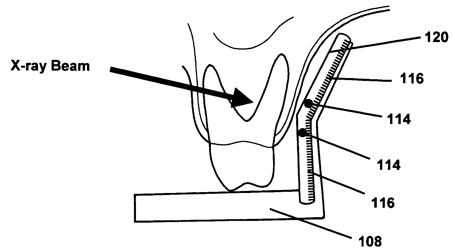
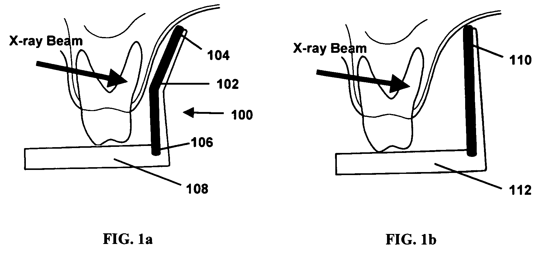
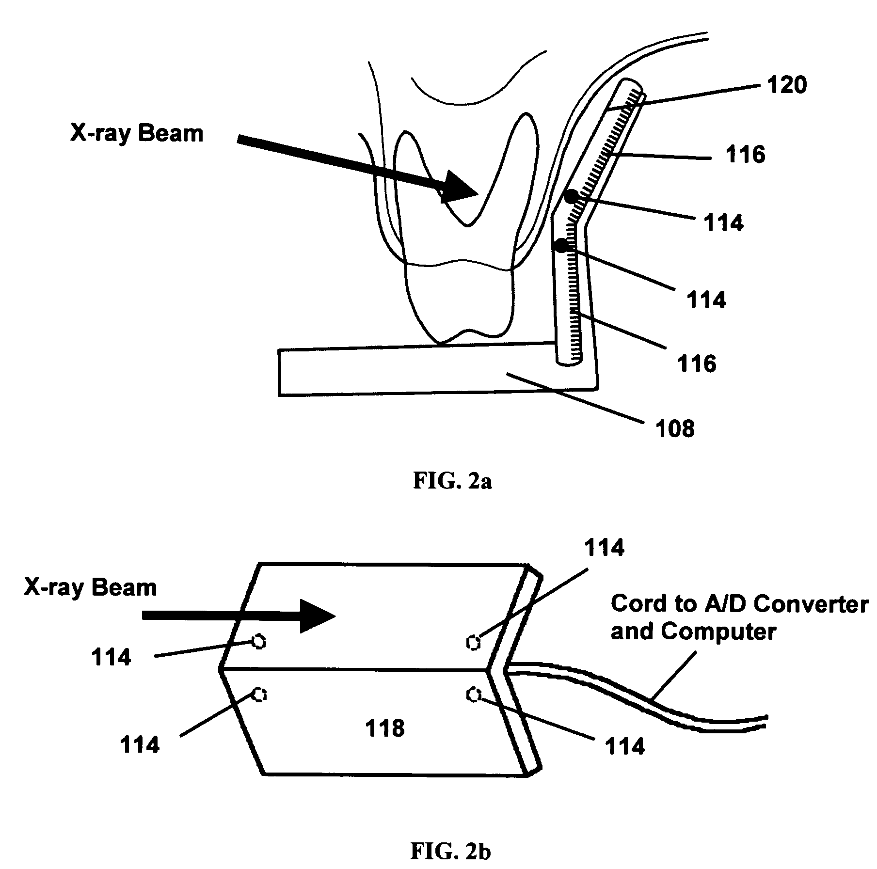
[0038]Referring now to the Figures, a sensor embodying the present invention is shown generally at 100 in FIG. 1a. The simplest implementation of an anatomically shaped radiographic sensor 102 embodying the present invention has two abutted imaging planes 104, 106, respectively, as shown in FIG. 1a which illustrates a cross-sectional view through the posterior portion of a patient's maxillary arch. A sensor holder / positioner 108 is shown for retention between a patient's teeth to hold sensor 102 in position during imaging procedures.

[0039]The specific angle of the two imaging planes 104, 106 relative to each other is not critical but empirical testing indicates that angles of about 20-40 degrees result in significant patient comfort relative to a single flat plane of equivalent imaging area. This configuration has been shown to significantly improve comfort and improve subject coverage compared to a standard sensor.

[0040]FIG. 1b is a similar view of a conventional radiographic senso...


PUM


Abstract

A system is described for obtaining intraoral radiographic images using an anatomically conforming sensor and a method is described for correcting the projective distortions caused by the inclination of the plane of the imaging sensor relative to the x-ray beam. The purpose of the described sensor system is to reduce patient discomfort as compared to conventional planar intra-oral x-ray sensors, which tend to impinge on sensitive tissues within the oral cavity. An additional purpose of the described system is to allow for better coverage of the subject by allowing the sensor to fit closer against the surrounding tissues.

Description

FIELD AND BACKGROUND OF THE INVENTION[0001]The present invention relates to an intraoral sensor design to be applicable to radiographic imaging sensors such as film, storage phosphor devices or solid-state direct capture devices (e.g. CCD's or CMOS based devices) or any other imaging sensor that can be used to produce radiographic images. Such sensors may be components of radiographic imaging systems that may include computers and video monitors for displaying radiographs. The present invention is also directed toward a method of correcting distortions appearing in the images of such radiographic imaging systems caused by the non-perpendicularity of the x-ray source relative to the imaging surface. Such analyses may be performed on a PC, which in turn may be part of a digital radiographic imaging system. The illuminating x-ray radiation source for such sensors and radiographic imaging systems is not the subject of the present invention.[0002]Radiographs are fundamental to most denta...

Claims


Application Information

Patent Timeline
Patent Type & Authority Patents(United States)
IPC IPC(8): H05G1/64A61B6/14G21K4/00
CPCA61B6/145
Inventor YOON, DOUGLAS C.CHEN, ADAM
Owner CYBER MEDICAL IMAGING INC
Why Eureka
Try Eureka