LASIK laminar flow system

a technology of air flow and laminar flow, which is applied in the field of air flow system, can solve the problems of over-hydrating the cornea, pulling air and accompanying contaminants into the eye, and post-operative infection of the ey

Inactive Publication Date: 2007-12-25
MEDLOGICS INC
View PDF207 Cites 16 Cited by
  • Summary
  • Abstract
  • Description
  • Claims
  • Application Information

AI Technical Summary

Problems solved by technology

The contaminants may become attached to the stroma and lead to a post-operative infection of the eye.
Unfortunately, aspirating the burned tissue pulls air an...

Method used


Image

  • LASIK laminar flow system
  • LASIK laminar flow system

Examples


Embodiment Construction

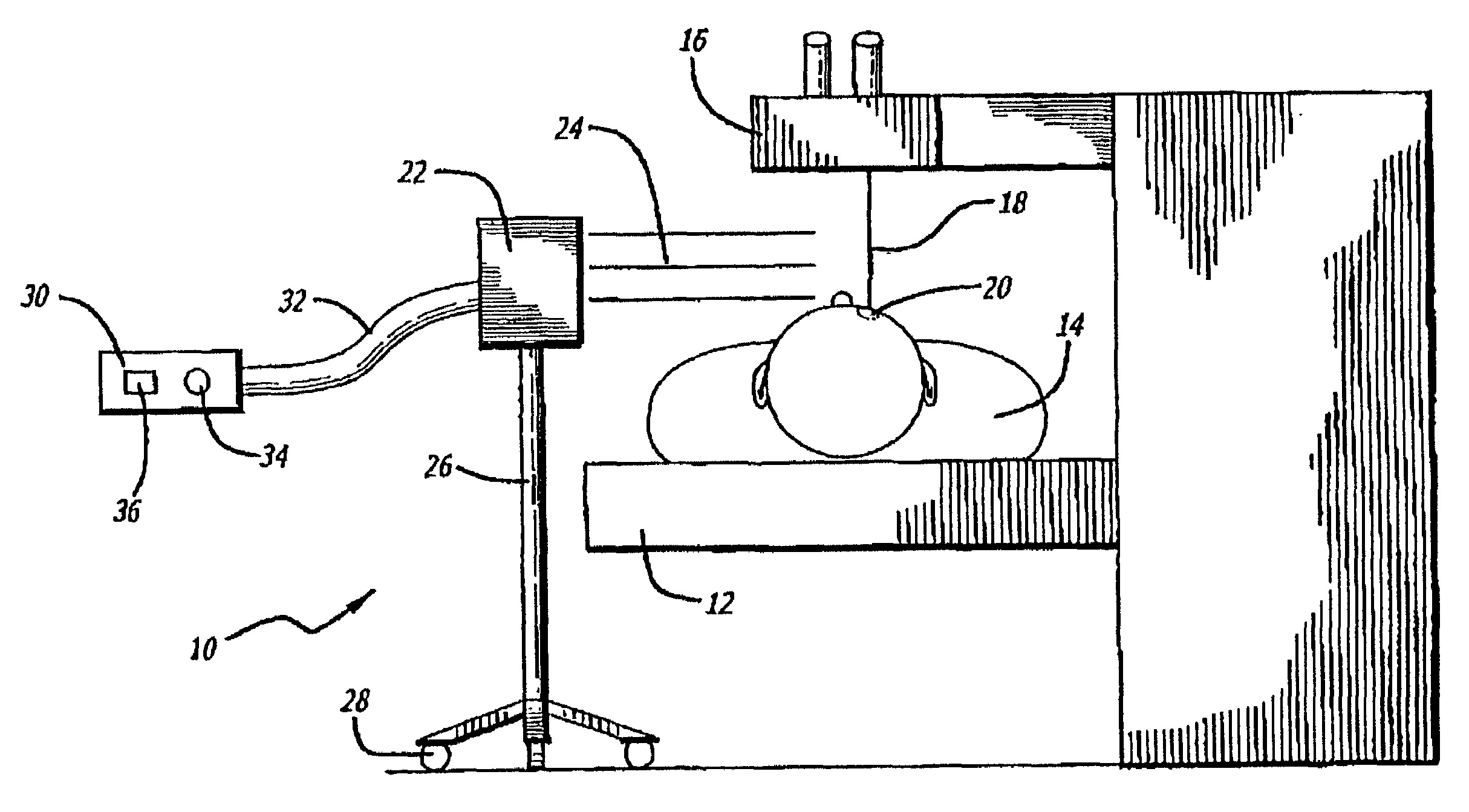
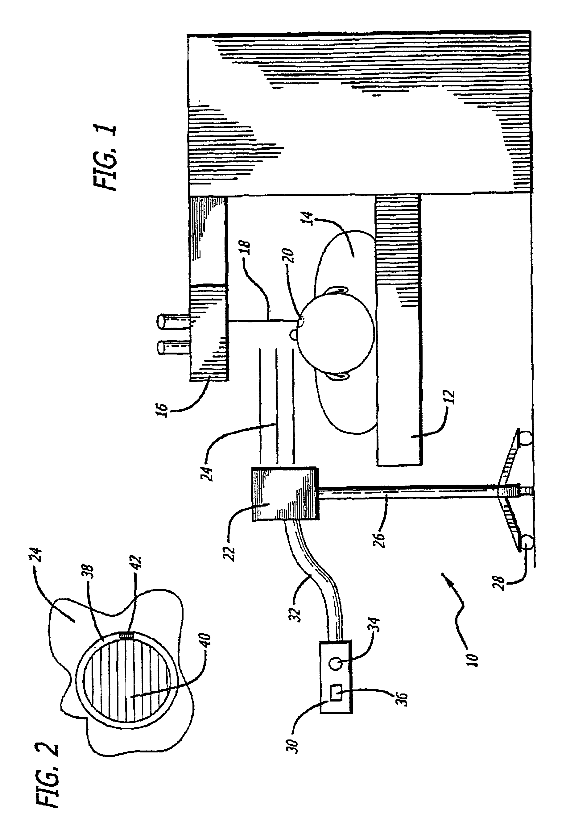
[0010]One embodiment of the present invention provides an airflow module that can direct a flow of air across the cornea of a patient during a LASIK procedure. The flow of air reduces the amount of contaminants that may become attached to the cornea during the procedure.

[0011]Referring to the drawings more particularly by reference numbers, FIG. 1 shows an embodiment of a system 10 of the present invention. The system 10 may include a patient support 12 that supports a patient 14. The patient support 12 may be a table. Alternatively, the support 12 may be a chair or any other support structure.

[0012]The system 10 may further include a light source 16 that directs a beam of light 18 onto a cornea 20 of the patient 14. The light source 16 may be an Eximer laser that emits light at a wavelength, which ablates corneal tissue.

[0013]The system 10 may include an airflow module 22 that directs a flow of air 24 across the patient's cornea 20. The airflow module 22 may be supported by a stand...


PUM


Abstract

A system that can be used to perform an ophthalmic procedure. The system may include a patient support that supports a patient and a light source which can direct a beam of light onto the patient's cornea. The system may also include an airflow module that directs a flow of air above the cornea. The flow of air reduces the amount of contaminants that may become attached to the cornea during the procedure.

Description

BACKGROUND OF THE INVENTION[0001]1. Field of the Invention[0002]The present invention relates to an air flow system that can reduce the amount of contaminates at the site of an ophthalmic procedure.[0003]2. Background Information[0004]There have been developed various techniques for correcting the vision of a patient. For example, there is a medical procedure that varies the curvature of a cornea using a laser. This procedure is commonly referred to as Laser in situ Keratomileusis (LASIK).[0005]In a LASIK procedure, a surgeon cuts the cornea to create a flap. The flap is peeled back to expose the stroma layer of the cornea. A laser beam is then directed into the stroma to ablate the cornea and vary the refractive characteristics of the eye. After the ablation step, the flap is placed back onto the cornea to complete the procedure. LASIK procedures are typically performed in a room that may have dust particles and other contaminants. The contaminants may become attached to the stroma...

Claims


Application Information

Patent Timeline
IPC IPC(8): A61N5/06A61B18/00A61F9/01
CPCA61F9/00804A61B2218/006A61F2009/00872
Inventor GUIMARAES, RICARDOROSS, ROD
Owner MEDLOGICS INC
Why Eureka
Try Eureka