Image acquisition/output apparatus and ophthalmology picture system using the same

a technology of image acquisition and output apparatus, applied in the field of microscope systems, can solve the problems of long recovery time, damage to the eyeball system, damage to the retina, etc., and achieve the effects of reducing side effects, ensuring the safety of operation, and slow recovery tim

Inactive Publication Date: 2007-03-29
KIM BONG HYUN
View PDF2 Cites 12 Cited by
  • Summary
  • Abstract
  • Description
  • Claims
  • Application Information

AI Technical Summary

Benefits of technology

[0022] According to the invention, wherein an affected part, i.e., an eye of the patient, is irradiated by near-infrared ray instead of visible light during operation, it is possible to reduce side effects, such as tissue damages caused when the affected part is irradiated by visible light, or slow recovery time after operation, thereby securing the safety of the operation.
[0023] Furthermore, the sense for the real of a display screen can be enhanced when an image of affected part obtained by the left and right side near-infrared sensors is displayed using a HMD or a three-dimensional monitor, and therefore it has an advantage that the operator can conduct a delicate and precise operation.
[0024] Moreover, an image of affected part

Problems solved by technology

However, there are several problems in this type of conventional microscope for ophthalmic operation as described in the following.
First, conventional microscope for ophthalmic operation uses visible light that is emitted from halogen light source as the illumination means to illuminate the affected part 20, but it has a problem in that the visible light may cause damage to the eye system, namely, the affected part 20, and long recovery time is required even when the operation has been finished.
In other words, in case where such visible light is used while performing ophthalmic operation, it may cause damage to the eyeball system, particularly to the retina.
Thus, medical reports reveal that the incidence of retinal damages due to visible light from the microscope during operation actually occupies approximately 7˜28% of ophthalmic operations that have been conducted until now.

Method used


Image

  • Image acquisition/output apparatus and ophthalmology picture system using the same
  • Image acquisition/output apparatus and ophthalmology picture system using the same
  • Image acquisition/output apparatus and ophthalmology picture system using the same

Examples


first embodiment

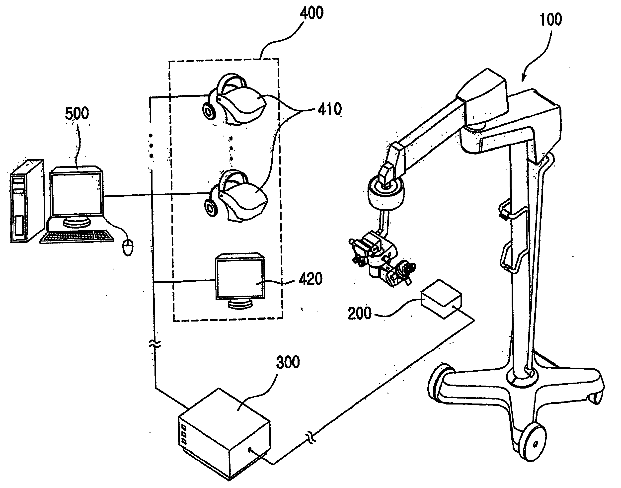
[0040]FIG. 2 is a view showing a picture system for ophthalmic operation according to the present invention.

[0041] As shown in FIG. 2, the picture system for ophthalmic operation according to the first embodiment of the present invention includes a near-infrared microscope 100, an image acquisition apparatus 200, an image distributor 300, a display apparatus 400, and a control / storage apparatus 500. According to the present invention, The microscope 100 irradiates near-infrared ray to an affected part and the image acquisition apparatus 200 acquires a three-dimensional image of affected part.

[0042] Here, near-infrared ray has the wavelength within the range of 750˜3000 nm, which is invisible by human eyes, and there is an advantage having hardly any side effects such as dazzling of the eyes or slow recovery time after operation, as compared with visible light having the same radiation energy.

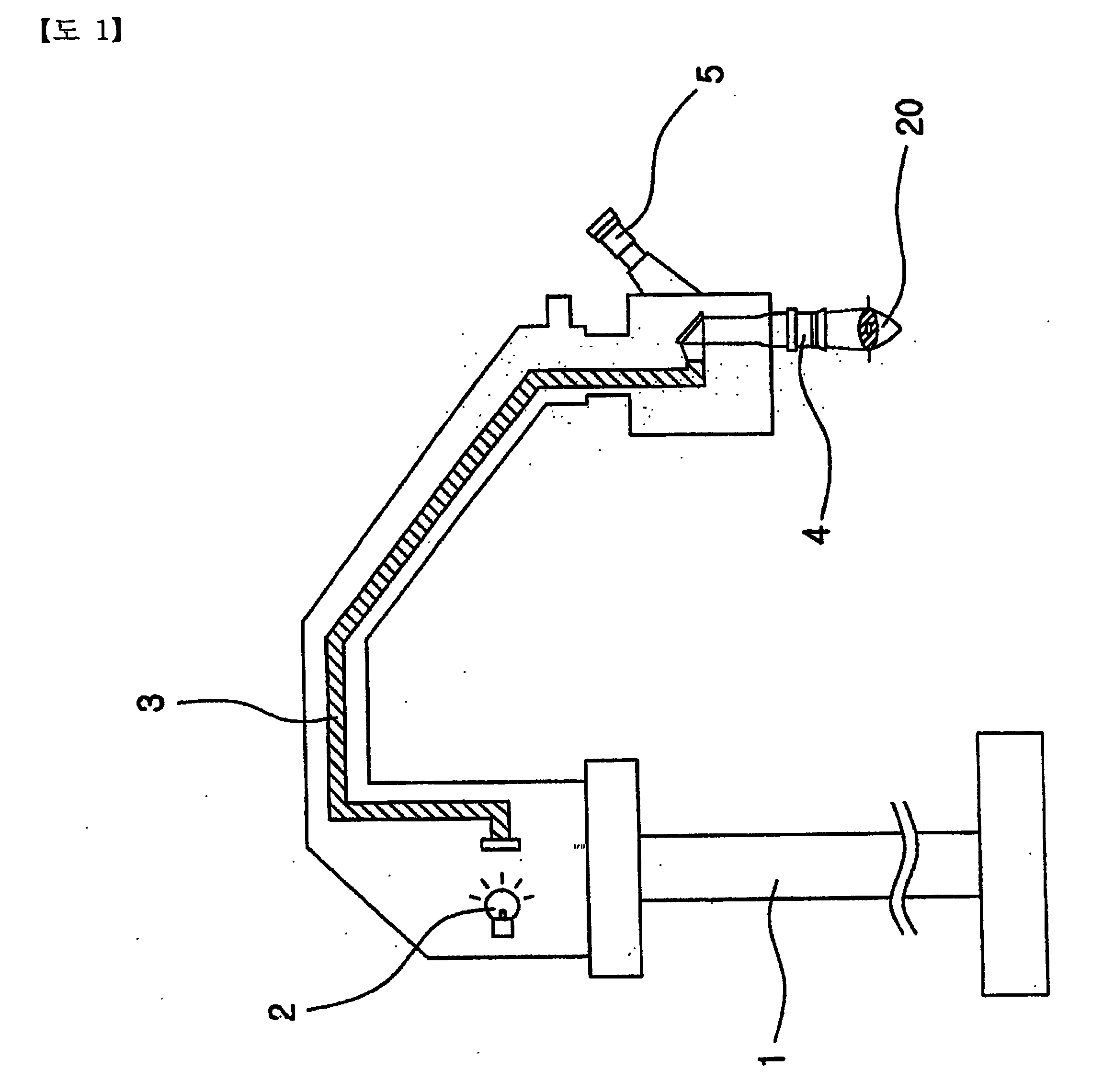
[0043]FIG. 3 is a configuration view schematically showing the near-infrared microscope 10...

second embodiment

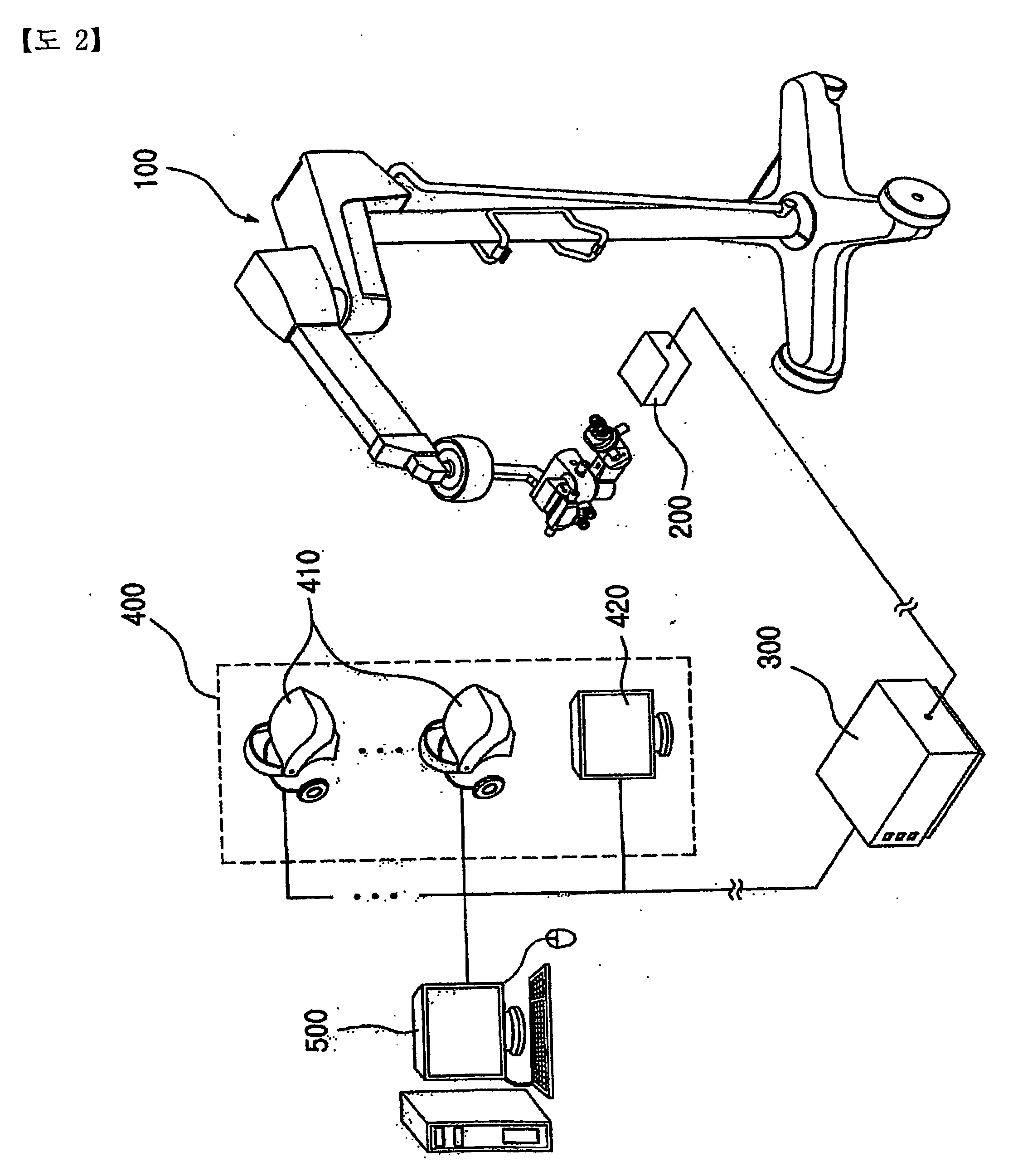
[0078]FIG. 9 is a configuration view showing a picture system for ophthalmic operation according to the present invention.

[0079] As shown in FIG. 9, the picture system for ophthalmic operation according to the second embodiment of the present invention includes an image acquisition / output apparatus 600, an image distributor 300, a display apparatus 400, and a control / storage apparatus 500.

[0080] The image acquisition / output apparatus 600 includes a main body 620, and a supporting member 610 which is combined with one side of the main body 620 for supporting the main body 620 to approach an affected part. In addition, the image acquisition / output apparatus 600 performs a function for acquiring near-infrared images of affected part using near-infrared ray, and converting the near-infrared images into electrical image signals to send them to an image distributor 300.

[0081]FIG. 10 is a configuration view schematically showing the main body 620 configuration of the image acquisition / ou...

third embodiment

[0090] Hereinafter, a picture system for ophthalmic operation according to the present invention will be described with reference to FIG. 11 through FIG. 13.

[0091]FIG. 11 is a perspective view showing a configuration of the ophthalmic operation near-infrared microscope according to the third embodiment of the present invention, and FIG. 12 is an exploded perspective view showing a configuration in which a near-infrared microscope 700 is combined with a beam splitter 800 and left / right side image acquisition apparatuses 910, 920 as shown in FIG. 11. Furthermore, FIG. 13 is a cross sectional view showing a construction of the beam splitter 800 of FIG. 12.

[0092] As shown in FIG. 11, the picture system for ophthalmic operation according to the third embodiment includes a near-infrared microscope 700, a beam splitter 800, a left side adaptor 830, a right side adaptor 840, a left side image acquisition apparatus 910, a right side image acquisition apparatus 920, an image distributor 300,...


PUM


Abstract

The present invention is related to an image acquisition/output apparatus and a picture system for ophthalmic operation using the same. The picture system for ophthalmic operation according to the present invention includes a near-infrared microscope for irradiating an affect part through an objective lens with near-infrared ray emitted from a light source, and transmitting near-infrared images formed by the objective lens to a first and a second ocular lenses, an image acquisition apparatus for converting near-infrared images transmitted to the first and the second ocular lenses into a first and a second electrical image signals for output, and a display apparatus for receiving the first and the second image signals and outputting them in three-dimensional images.

Description

TECHNICAL FIELD OF THE INVENTION [0001] The present invention relates to a microscope system, more particularly, to an image acquisition / output apparatus for acquiring an image using near-infrared ray and outputting the acquired image, and a microscope system for ophthalmic operation which displays the acquired near-infrared image in 3-dimensions. BACKGROUND OF THE INVENTION [0002] In general, ophthalmic operations mean eyesight correction surgeries such as lasik, lasek, wavefront and excimer laser, and eye disease treatments such as operations on cataract and glaucoma. [0003] For such ophthalmic operation, high precision and accuracy are required, since it is an important operation to treat human eyes and the size of an affected part is relatively small. [0004] Accordingly, during this ophthalmic operation, there should be provided a picture system for ophthalmic operation to keep observation closely on the affected part and the progress made by the operation, and a microscope for ...

Claims


Application Information

Patent Timeline
IPC IPC(8): A61B3/14A61B3/13
CPCA61B3/132G02B26/007G02B21/0012A61B3/13
Inventor KIM, BONG-HYUN
Owner KIM BONG HYUN
Why Eureka
Try Eureka