Single axis illumination for multi-axis imaging system

a multi-axis imaging and single-axis technology, applied in the direction of instruments, optical elements, discharge tubes/lamp details, etc., can solve the problems of reducing system efficiency, wasting light, and affecting the image quality of objects under high magnification, so as to improve telecentricity and modify the spatial or angular properties of light.

Inactive Publication Date: 2007-12-25
DMETRIX INC
View PDF20 Cites 16 Cited by
  • Summary
  • Abstract
  • Description
  • Claims
  • Application Information

AI Technical Summary

Benefits of technology

[0016]For dark-field illumination, an annular amplitude mask having a dark central portion is placed at the light source or a conjugate plane to the source. For phase contrast microscopy, annular phase masks are placed at the back focal planes of respective first, objective lenses in respective arranged imaging elements, or planes conjugate thereto; preferably, a corresponding annular amplitude mask is placed between the light source and the object at the front focal plane of a condenser lens in the illumination system. Similarly, for Hoffman modulation c

Problems solved by technology

The stage manipulation and the consequent time required to image an object under high magnification is particularly troublesome in pathology analysis since the diagnostic information in the tissue may be located in only a small portion of the object that is being imaged.
That is, if the illumination system transmits light to the object at angles greater than the acceptance angle of the imaging system, some of the light may be wasted, which reduces system efficiency.
On the other hand, if the illumination system transmits light over a narrower angular range, that is, one that does no

Method used


Image

  • Single axis illumination for multi-axis imaging system
  • Single axis illumination for multi-axis imaging system
  • Single axis illumination for multi-axis imaging system

Examples


Embodiment Construction

[0040]The illumination systems and methods of the present invention are adapted for use with mult-axis imaging systems, particularly microscope arrays, and more particularly array microscopes. Array microscopes, which are a recent development, may be used, for example, to scan and image entire tissue or fluid samples for use by pathologists. Individual imaging elements of array microscopes are closely packed and have a high numerical aperture. This enables the capture of high-resolution microscopic images of the entire sample in a short period of time by scanning the specimen with the array. It also presents novel illumination challenges which are met by the present invention.

1. Microscope Arrays

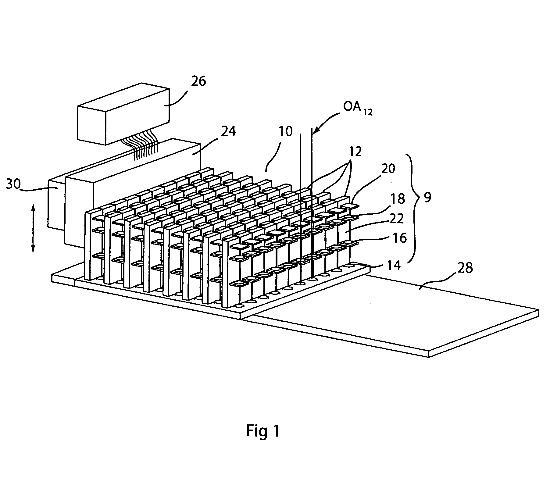
[0041]An exemplary microscope array 10 is shown in FIG. 1. The microscope array 10 comprises an imaging lens system 9 having a plurality of individual imaging elements 12. Each imaging element 12 may comprise a number of optical elements, such as the elements 14, 16, 18 and 20. In this examp...


PUM


Abstract

A single-axis illumination system for a multiple-axis imaging system, particularly an array microscope. A single-axis illumination system is used to trans-illuminate an object viewed with an array of imaging elements having multiple respective axes. The numerical apertures of the imaging elements are preferably matched to the numerical aperture of the illumination system. For Kohler illumination, the light source is placed effectively at the front focal plane of the illumination system. For critical illumination, the light source is effectively imaged onto the object plane of the imaging system. For dark field illumination, an annular light source is effectively provided. For phase contrast microscopy, an annular phase mask is placed effectively at the back focal plane of the objective lens of the imaging system and a corresponding annular amplitude mask is provided effectively at the light source. For Hoffman modulation contrast microscopy, an amplitude mask is placed effectively at the back focal plane of the objective lens of the imaging system and a slit is provided at a source of light of the illumination system. Structured illumination and interferometry, and a secondary source, may also be used with trans-illumination methods and apparatus according to the present invention.

Description

[0001]This invention relates to trans-illumination for imaging systems, particularly to a single axis trans-illumination system for a multi-axis imaging system, and more particularly for a microscope array comprising a plurality of optical imaging elements having respective optical axis.BACKGROUND OF THE INVENTION[0002]In imaging systems, particularly microscopy, adequate and appropriate illumination of the object to be imaged is essential. There must be enough light provided to the object or specimen to be viewed to permit the viewer to discern features of the object. In addition, the manner in which the light is provided to the object makes a difference in what features can be detected and the contrast with which they are imaged.[0003]An ordinary microscope typically employs a compound imaging lens system for imaging the object. Any number of lenses or other optical elements such as polarizers, collimators, spreading optics, mirrors, and splitters may be included in the lens syste...

Claims


Application Information

Patent Timeline
IPC IPC(8): H01J3/16G02B21/06G02B21/00
CPCG02B21/06G02B21/002
Inventor LIANG, CHEN
Owner DMETRIX INC
Why Eureka
Try Eureka