Antenna device mounted on vehicle

an antenna device and vehicle technology, applied in the direction of antenna details, antenna adaptation in movable bodies, antennas, etc., can solve the problems of unsatisfactory stability of electrical connection and complicated work, and achieve the effect of stable electrical connection

Inactive Publication Date: 2007-12-25
YOKOWO CO LTD
View PDF5 Cites 14 Cited by
  • Summary
  • Abstract
  • Description
  • Claims
  • Application Information

AI Technical Summary

Benefits of technology

[0007]It is therefore an object of the invention to provide an antenna device for vehicle, that is small in the number of parts and provides stable electrical connection.
[0013]With this configuration, the opposing inner faces of the first bracket-shaped portion are brought by their own elasticity, into elastic contact with the opposite outer faces of the second bracket-shaped portion which is electrically connected to the antenna element. Since no component corresponding to the coiled spring of the conventional structure is necessary, the number of components is reduced accordingly and assembling work is made easier. Further, since the first conductive member is brought into elastic contact with the second conductive member, electrical conduction is established through the two sets of faces and hence the electrical connection is made more stable.
[0014]The antenna device may further comprise a shaft penetrating the first conductive member and the second conductive member, so that the second conductive member is pivotable about the shaft. In this case, the structure allowing the second conductive member to be pivoted can be made simple.
[0016]In this case, the antenna body can be pivoted relative to the first conductive member and retained in a prescribed posture without increasing the number of component.
[0020]In this case, the projections of the second conductive member can easily be guided, by way of the grooves, to the positions where they fit into the recesses, respectively.

Problems solved by technology

In addition, assembling work needs to be performed in a state that the coiled spring 24 is compressed and the work is complicated.
Further, since elastic contact and electric conduction between the first and second feeder plates 14 and 18 are established by the single pair of faces, the stability of electrical connection is not always satisfactory.

Method used


Image

  • Antenna device mounted on vehicle
  • Antenna device mounted on vehicle
  • Antenna device mounted on vehicle

Examples


Embodiment Construction

[0033]Embodiments of the invention will be described below in detail with reference to the accompanying drawings.

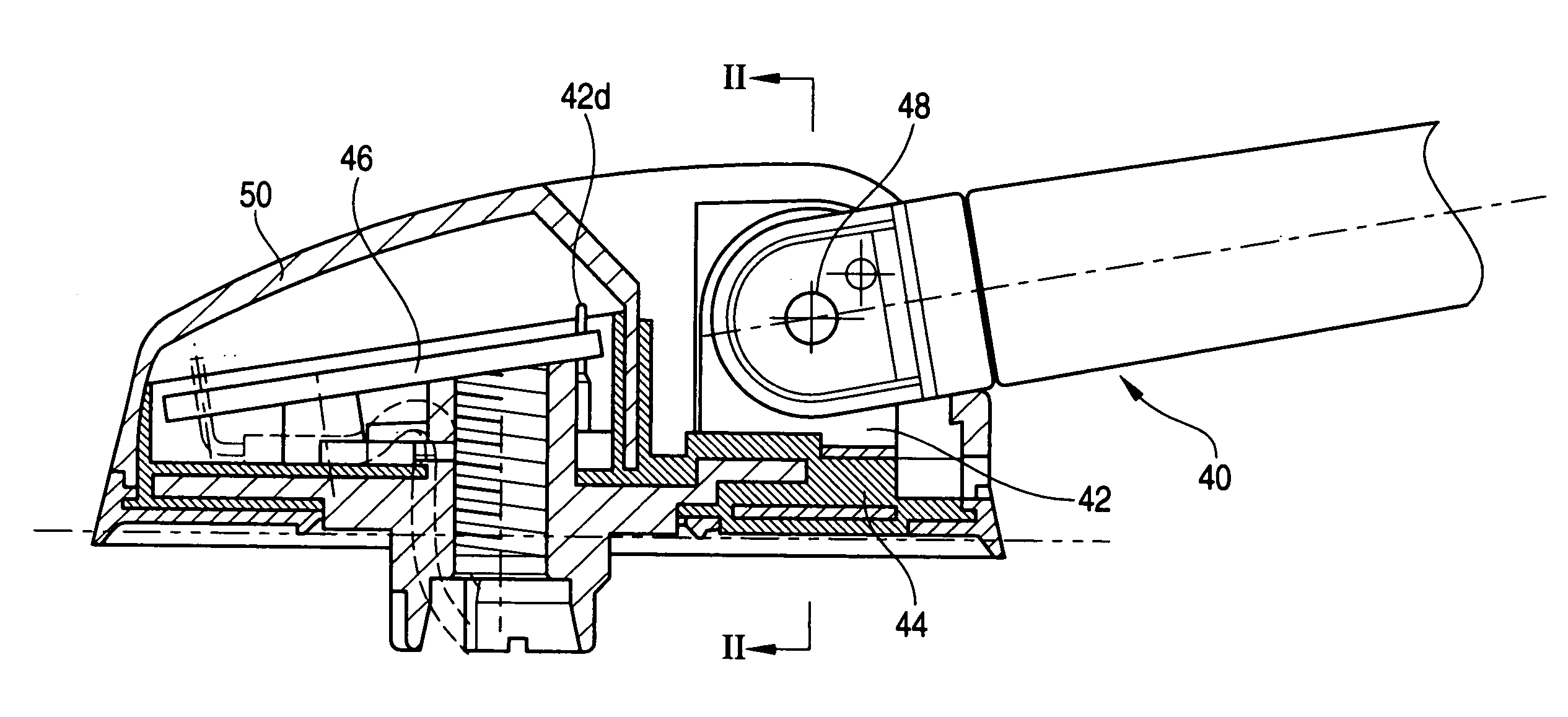
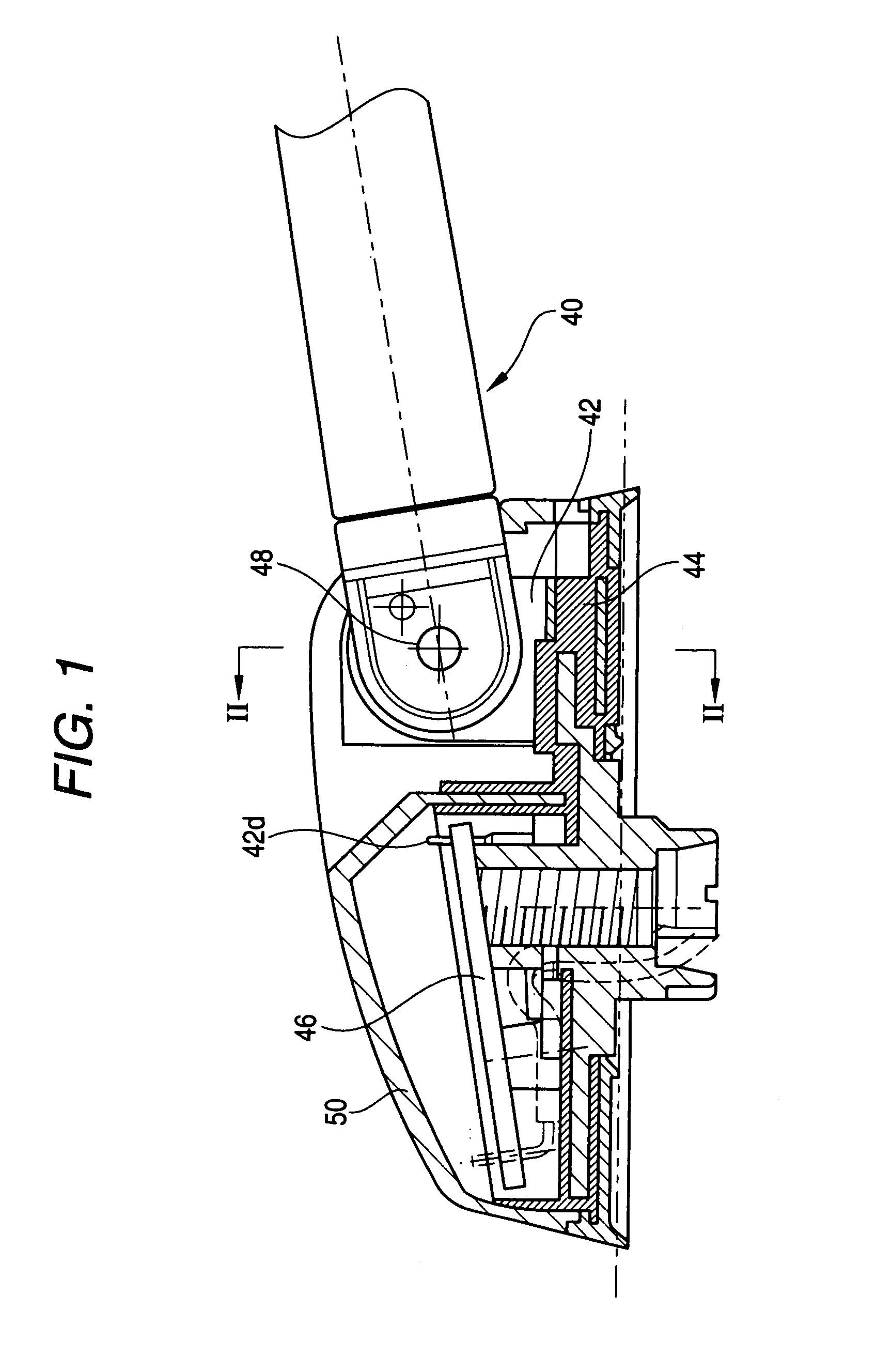
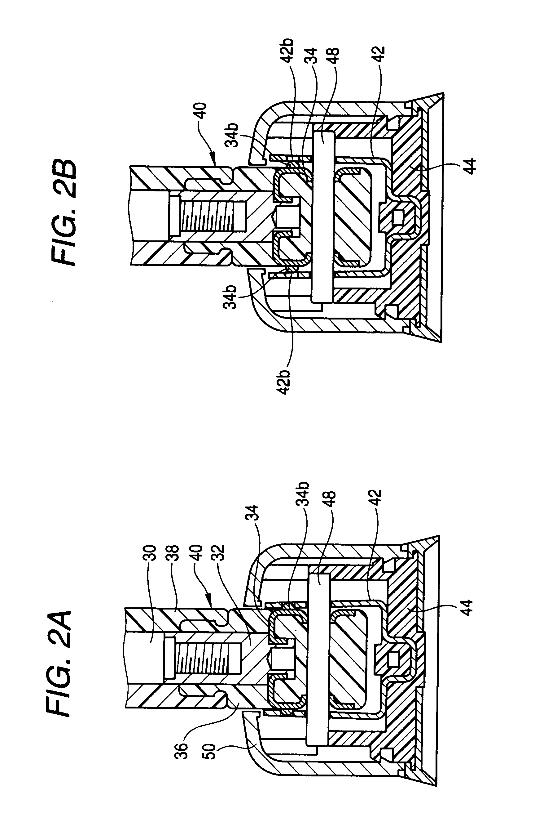
[0034]In an antenna device according to one embodiment of the invention, the proximal end of an antenna element 30 is screwed into an insertion fitting 32 which is conductive. A bracket-shaped pivot plate 34 is fixed to the insertion fitting 32 by caulking with its opening down and electrical conduction is thereby established between them. A resin mold 36 is formed with the insertion fitting 32 and the pivot plate 34 inserted therein. Both side walls of the bracket-shaped pivot plate 34 are exposed and serve as outer walls of the resin mold 36. Part of the resin mold 36 and the antenna element 30 are covered with a cover 38 made of an insulative resin, whereby a pivotable antenna body 40 is formed.

[0035]As shown in FIG. 4 in detail, the pivot plate 34 is formed as follows. A bracket-shaped part is formed by working on a conductive metal sheet. Holes 34a for shaft insertio...


PUM


Abstract

A base member is adapted to be mounted on a vehicle body. A proximal end of a rod-shaped antenna body is pivotably provided on the base member. The antenna body includes an antenna element. A first conductive member is disposed in the base member and provided with a first bracket-shaped portion having elasticity. A second conductive member is electrically connected to the antenna element and provided with a second bracket-shaped portion. The second conductive member is pivotably fitted with the first conductive member while opposite outer faces of the second bracket-shaped portion is brought into elastic contact with opposing inner faces of the first bracket-shaped portion.

Description

BACKGROUND OF THE INVENTION[0001]The present invention relates to an antenna device adapted to be mounted on a vehicle body and in which an antenna body is pivotably provided.[0002]FIG. 5 shows an example of this kind of antenna device which is disclosed in Japanese Patent Publication No. 2003-32015A.[0003]A single plate-shaped first feeder plate 14 which is electrically connected to the proximal end of an antenna element 12 is disposed in a proximal end portion of a pivotable antenna body 10. The first feeder plate 14 is conductive and elastic. A single plate-shaped second feeder plate 18 is disposed in a base member 16. The second feeder plate 18 is conductive. A terminal portion 18a projecting from the second feeder plate 18 is electrically connected in a proper manner to a circuit board 20 which is provided in the base member 16.[0004]A shaft 22 is made to penetrate through the first and second feeder plates 14 and 18 in a state that they are opposed to each other, whereby the f...

Claims


Application Information

Patent Timeline
Patent Type & Authority Patents(United States)
IPC IPC(8): H01Q1/32
CPCH01Q1/3275H01Q1/1207H01Q1/20
Inventor GORAI, TATSUOOHNO, SADAO
Owner YOKOWO CO LTD
Why Eureka
Try Eureka