
Lubrication system

a technology of lubrication system and grease reservoir, which is applied in the direction of liquid/fluent solid measurement, machines/engines, instruments, etc., can solve the problem of nevertheless having certain limitations

Inactive Publication Date: 2008-01-01
METCO ENG
View PDF21 Cites 34 Cited by
  • Summary
  • Abstract
  • Description
  • Claims
  • Application Information

AI Technical Summary

Benefits of technology

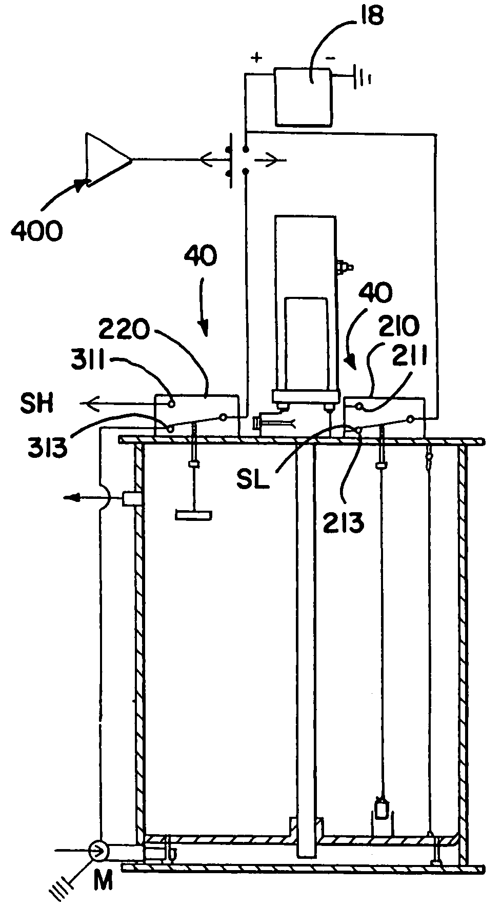
[0005]The reservoir further comprises an alarm system disposed proximate to the top. The alarm comprises an electrical switch operably associated with the follower and generates a signal when the follower is at a predetermined location in the body. The body further comprises an inner surface. In one embodiment, the follower has a circumferential lip that engages and preferably seals the inner surface of the body. The lip acts as a wiper or squeegee to remove lubricant from the inner surface of the body as the follower moves therein. The lubrication system also provides means for preventing the follower from abutting the bottom of the reservoir. In one embodiment of the lubrication system, the reservoir comprises an overflow passage through the body proximate to the top.

Problems solved by technology

While the lubrication systems of the prior art provide a number of advantageous features, they nevertheless have certain limitations.

Method used


Image

  • Lubrication system
  • Lubrication system
  • Lubrication system

Examples


Embodiment Construction

[0024]While this invention is susceptible of embodiments in many different forms, and will herein be described in detail, preferred embodiments of the invention are disclosed with the understanding that the present disclosure is to be considered as exemplifications of the principles of the invention and are not intended to limit the broad aspects of the invention to the embodiments illustrated.

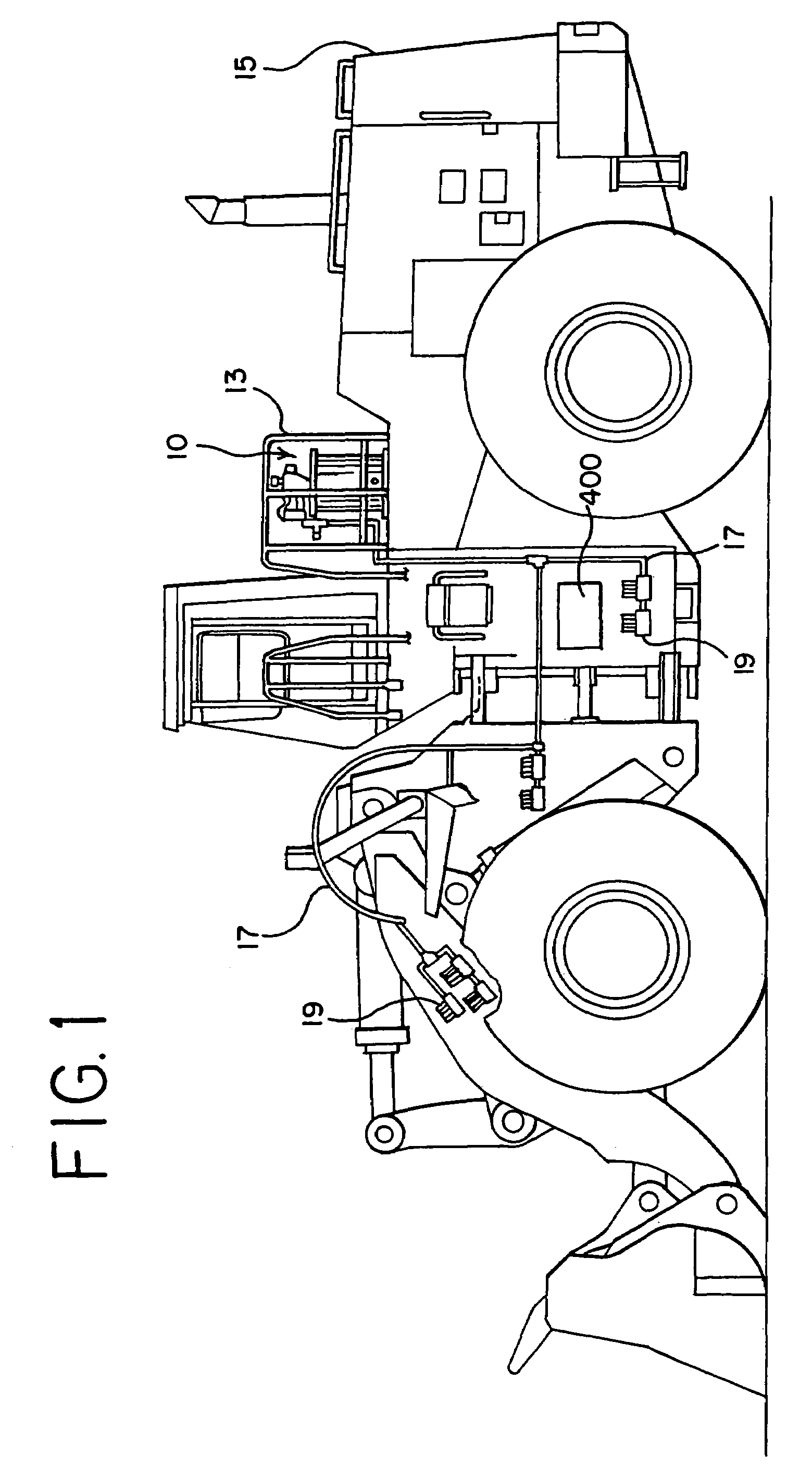
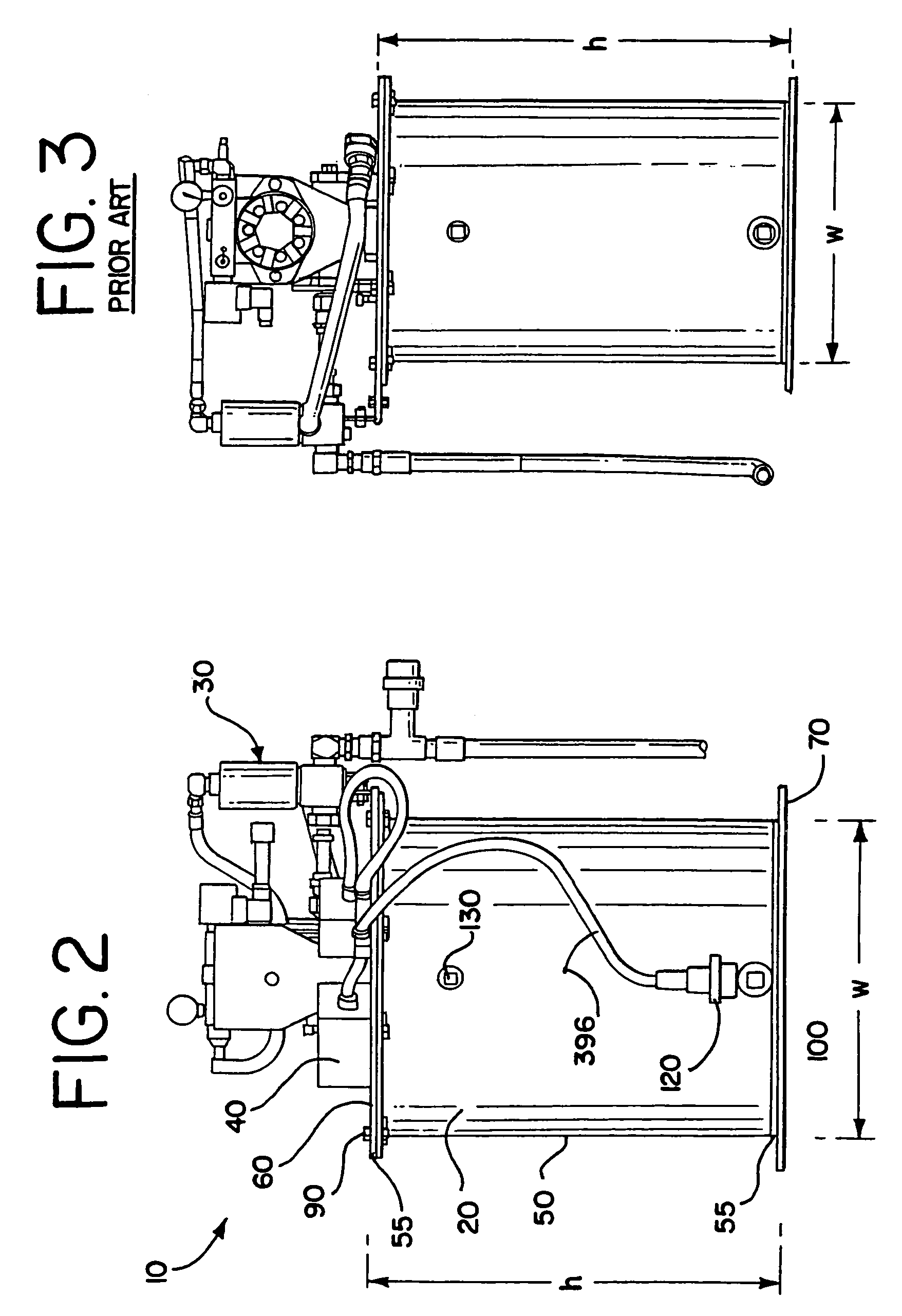
[0025]FIG. 1 is a side elevation view of a lubrication system 10 mounted on a construction vehicle 15. The lubrication system 10 generally includes a lubrication reservoir or tank 20, a pump assembly 30, and an alarm system 40, all of which can be seen in FIGS. 2 and 6 through 8. As one use of the invention, the lubrication system 10 comprises part of a bearing dosage system, and more particularly part of a lubricant metering device such as for delivering grease to the fittings, joints and bearings of industrial construction and mining equipment. As further shown in FIG. 1, the lubrication sys...


PUM


Abstract

The present invention is directed to lubrication system having a reservoir having a body. A follower is moveably disposed in the body. The system further comprises an alarm system having an electrical switch operably associated with the follower. The alarm generates a signal when the follower is at a predetermined location in the body. The alarm system may generate a signal when the follower is at a lower location in the body such as when the reservoir has an amount of lubricant representing a predetermined amount of usage time remaining. The alarm system may also generate a signal when the follower is at an upper location in the body such as when the reservoir is filled with lubricant wherein the signal acts to automatically interrupt the fill of lubricant.

Description

TECHNICAL FIELD[0001]The invention relates generally to a lubrication system for industrial equipment such as in a bearing dosage system, and more particularly to a grease reservoir that lubricates the fittings, joints and bearings of industrial construction or mining equipment such as loaders, excavators, crushers, and haul trucks.BACKGROUND OF THE INVENTION[0002]Lubrication systems are well-known in the art, and are generally used to deliver grease to locations on various types of equipment. For example, lubrication systems are used to deliver grease to industrial and mining equipment.[0003]While the lubrication systems of the prior art provide a number of advantageous features, they nevertheless have certain limitations. As described herein, the present invention seeks to overcome certain of these limitations and other drawbacks of the prior art, and to provide new features not heretofore available.SUMMARY OF THE INVENTION[0004]The present invention provides a lubrication system ...

Claims


Application Information

Patent Timeline
IPC IPC(8): G01F23/00
CPCG01F23/70F01M1/18G01F23/76F16N7/385F16N19/00F16N19/003F16N29/04
Inventor MURPHY, SR., PATRICK J.
Owner METCO ENG
Learn More