Irreversible plug assembly

a plug assembly and reversible technology, applied in the direction of heat exchanger fastening, pipe elements, light and heating apparatus, etc., can solve the problem of plug assembly failur

Inactive Publication Date: 2008-01-01
DOUGLAS L HOLLAENDER ENTERPRISES
View PDF15 Cites 29 Cited by
  • Summary
  • Abstract
  • Description
  • Claims
  • Application Information

AI Technical Summary

Benefits of technology

[0004]The present invention is premised on the realization that a plug assembly for use in heat exchanger tubes, which can be irreversibly set in a tube, includes a tapered wedge and a sleeve adapted to fit over the tapered wedge. The wedge includes exterior annular grooves and the sleeve includes interior annular grooves. Expansion rings are located in the grooves in the wedge or in the sleeves, which permit the sleeve to move i

Problems solved by technology

But, this is very expensive.
Mechanical devices can also be used; but, in high-pressure application

Method used


Image

  • Irreversible plug assembly
  • Irreversible plug assembly
  • Irreversible plug assembly

Examples


Embodiment Construction

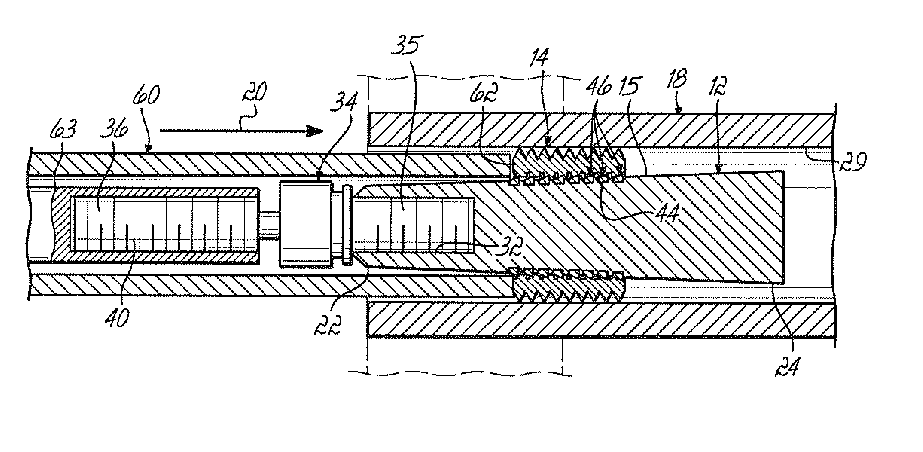
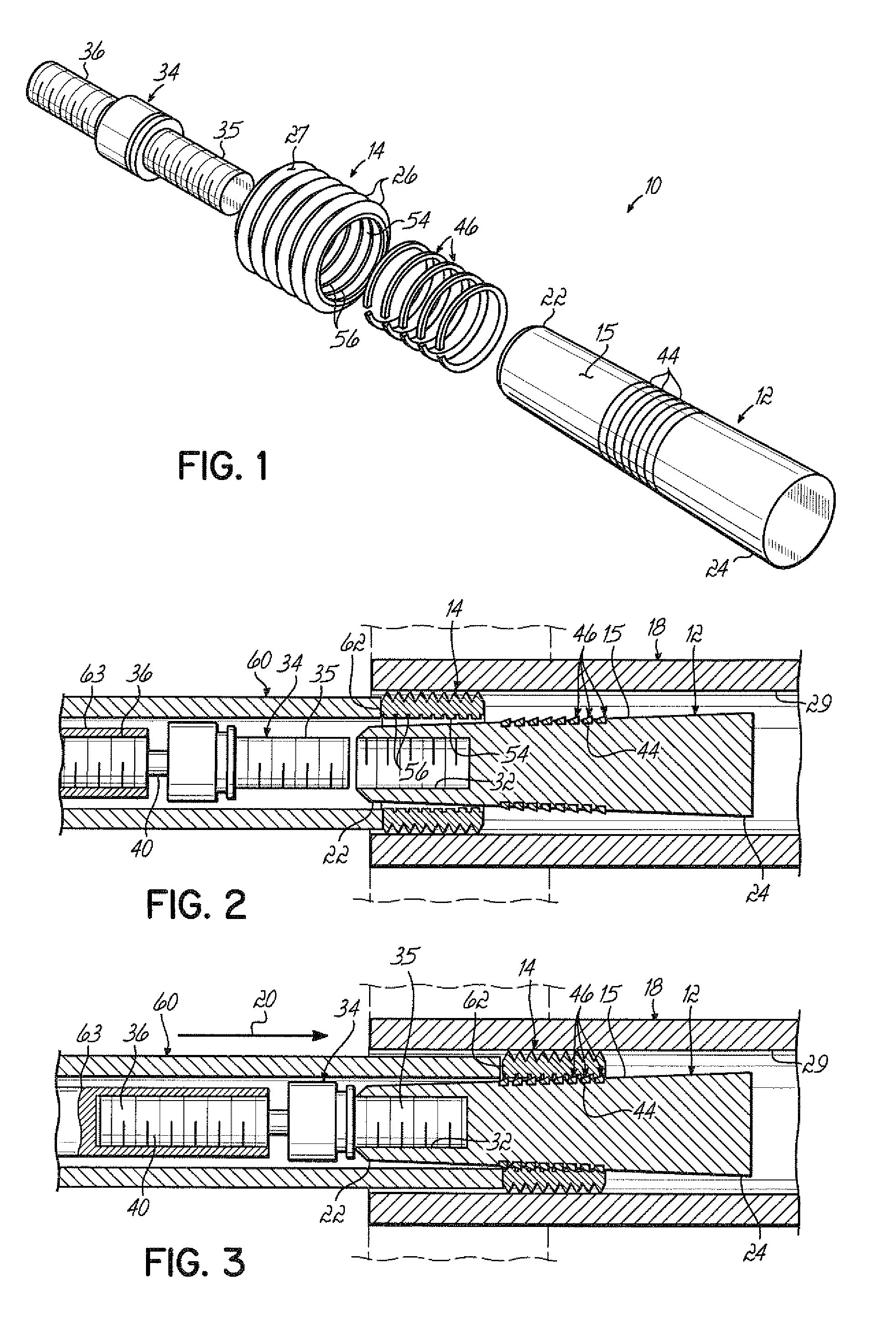
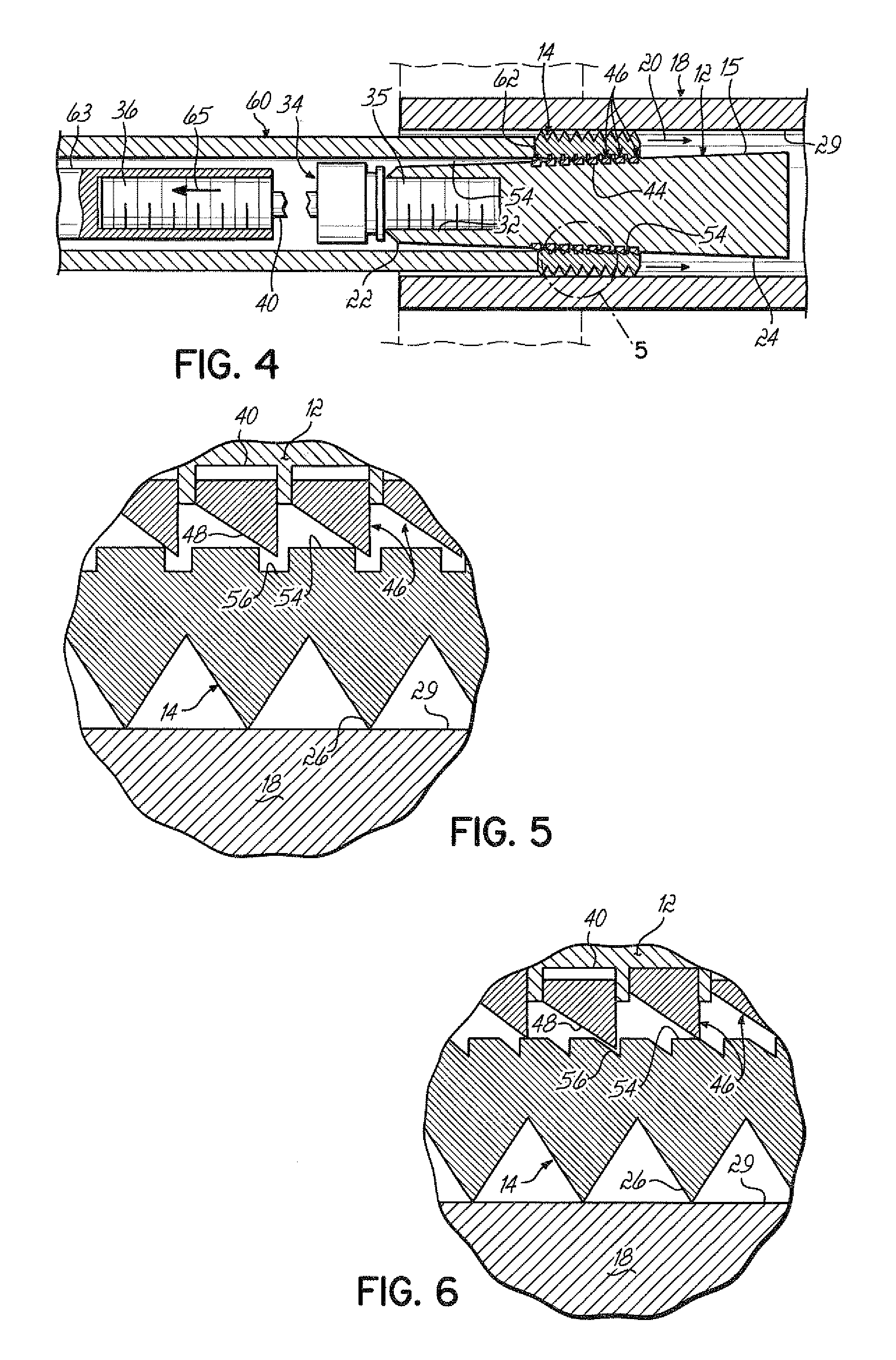
[0012]As shown in FIG. 1, the present invention is a plug assembly 10 having a tapered rod or wedge 12 having an outer tapered surface 15 and a sleeve 14. Plug assembly 10 fits into a tube 18, such as a tube of a heat exchanger. Moving sleeve 14 from a smaller diameter portion 22 of wedge 12 to a larger diameter portion 24 in the direction of arrow 20 causes the sleeve 14 to expand, forcing the ridges 26 on the external surface 27 of sleeve 14 to engage the inner surface 29 of tube 18. The force between the ridges 26 and the tube surface 29 seals tube 18.

[0013]The wedge 12, at its narrow diameter portion 22, includes an internally threaded opening 32. A connector rod 34 connects to the wedge 12 with a first externally threaded portion 35 screwed into the internally threaded opening 32. The connector rod 34 further includes a second externally threaded portion 36 separated from the first externally threaded portion by a narrowed connector portion 40.

[0014]The tapered surface 15 of we...


PUM


Abstract

A plug assembly for a tube includes a tapered wedge and a sleeve. The sleeve fits over the wedge and is placed in a tube. Relative movement of the wedge and the sleeve causes the sleeve to expand and plug the tube. The exterior surface of the wedge and the interior surface of the sleeve include annular grooves. One or more compression rings in either the grooves in the sleeve or wedge permit motion of the sleeve relative to the wedge only toward the large diameter portion of the wedge. This prevents the sleeve from separating from the wedge after being installed in a tube.

Description

BACKGROUND OF THE INVENTION[0001]It is often necessary to plug or seal a tube or circular opening. Plugs can be used to seal bores formed in diesel engines, such as the plug disclosed in U.S. Pat. No. 6,053,992. Plugs are also used to seal tubes in heat exchangers. There are a wide variety of different methods used to seal such tubes. In certain applications, explosive devices are used to seal off a tube. But, this is very expensive. Mechanical devices can also be used; but, in high-pressure applications, these may fail.[0002]A potentially useful plug to seal tubes is disclosed in Hall U.S. Pat. No. 5,189,789. This discloses the use of a memory metal or Nitinol plug. Memory metals are alloys that undergo a reversible transformation from an austenitic state to a martensitic state with changes in temperature. At colder temperatures, the alloy enters the martensitic state and reverts to the austenitic state at higher temperatures. A plug in the martensitic state can be bent or shaped. ...

Claims


Application Information

Patent Timeline
IPC IPC(8): F16L55/10
CPCF16L55/11F28F2220/00F28F2275/08F28F2275/16F28F2275/18F16L55/132F16L55/13
Inventor ADELMAN, ROGER
Owner DOUGLAS L HOLLAENDER ENTERPRISES
Why Eureka
Try Eureka