
Equipment for vibration damping of a lift cage

a technology for damping equipment and lift cages, which is applied in the direction of lifts, transportation and packaging, building lifts, etc., can solve the problems of undesired vibration, unevenness of guide rails, and production of transverse vibrations, and achieve the effect of simple operation

Active Publication Date: 2008-01-01
INVENTIO AG
View PDF15 Cites 16 Cited by
  • Summary
  • Abstract
  • Description
  • Claims
  • Application Information

AI Technical Summary

Benefits of technology

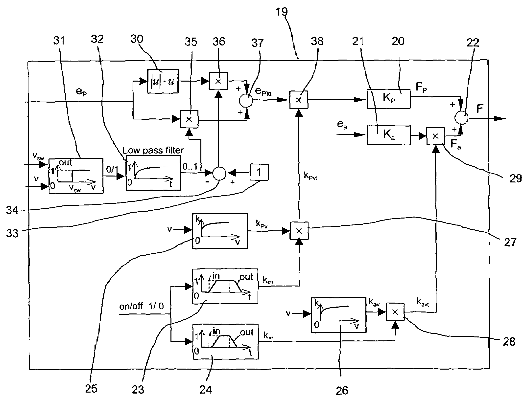
The present invention aims to prevent vibrations and shocks during the starting up, stopping, and loading and unloading of a lift cage. The invention achieves this by designing an amplification device that can adapt to non-linear processes, such as vibrations and shocks, by speed- or time-dependent weighting of error signals or regulating deviations. The regulating device can also comprise two internal regulators, namely a position regulator and an acceleration regulator, to separately regulate the guide elements and suppress vibrations. The invention provides a simple and effective solution to prevent vibrations and shocks during the operation of lift cages.

Problems solved by technology

The causes of vibrations in that case can be, in particular, unevennesses in the guide rails and forces produced by the slipstream about the cage.
Beyond that, lateral traction forces transmitted by the traction cables or sudden positional changes of the load during travel can produce transverse vibrations.
However, the consequence of such an assumption is that undesired vibrations can arise when the regulator is switched on at the beginning and end of travel of the lift.
The cause of such vibrations is that non-linear changes in the state of the system are present and cannot be controlled by the linear and time-invariable behaviour of the regulator.

Method used


Image

  • Equipment for vibration damping of a lift cage
  • Equipment for vibration damping of a lift cage
  • Equipment for vibration damping of a lift cage

Examples


Embodiment Construction

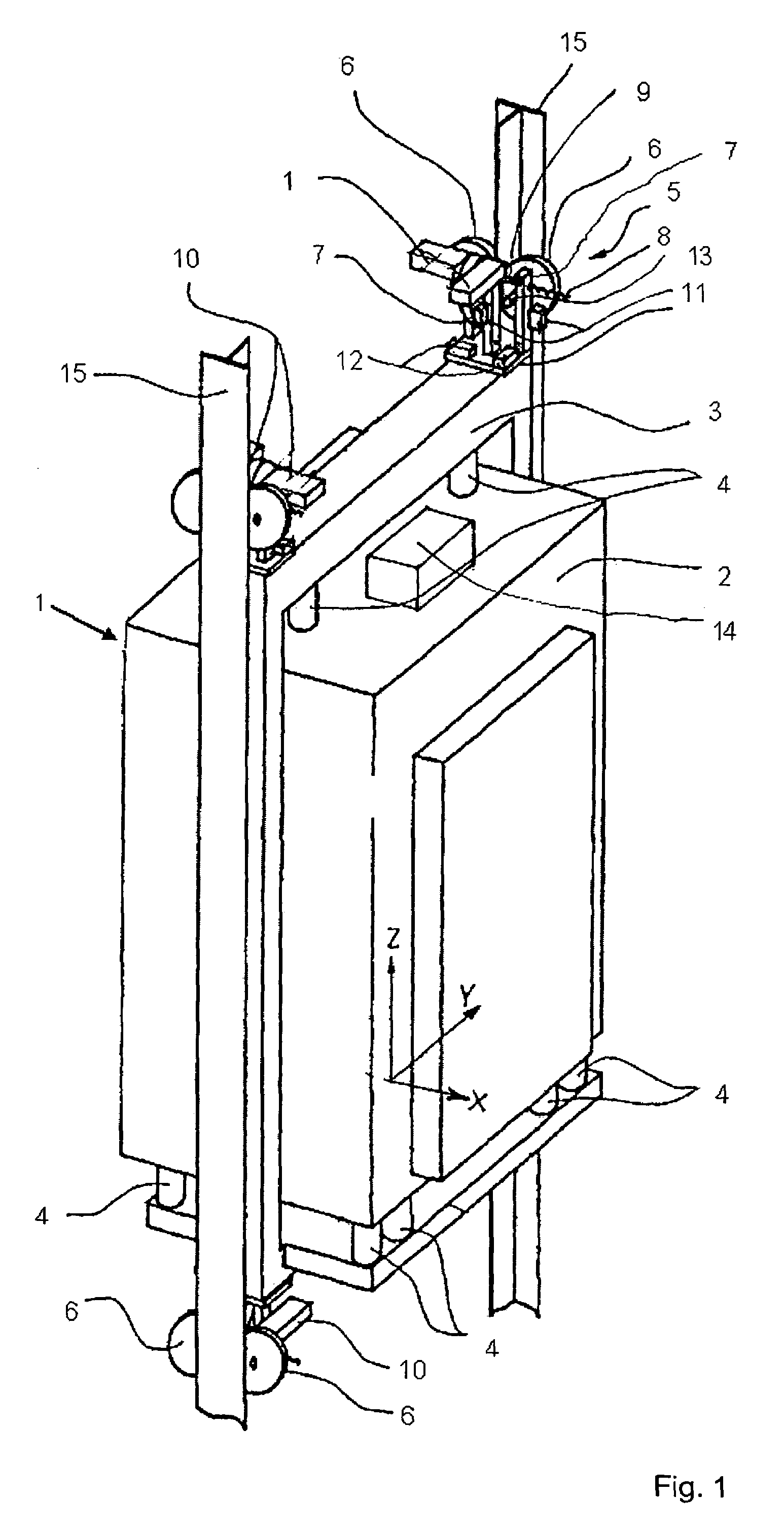
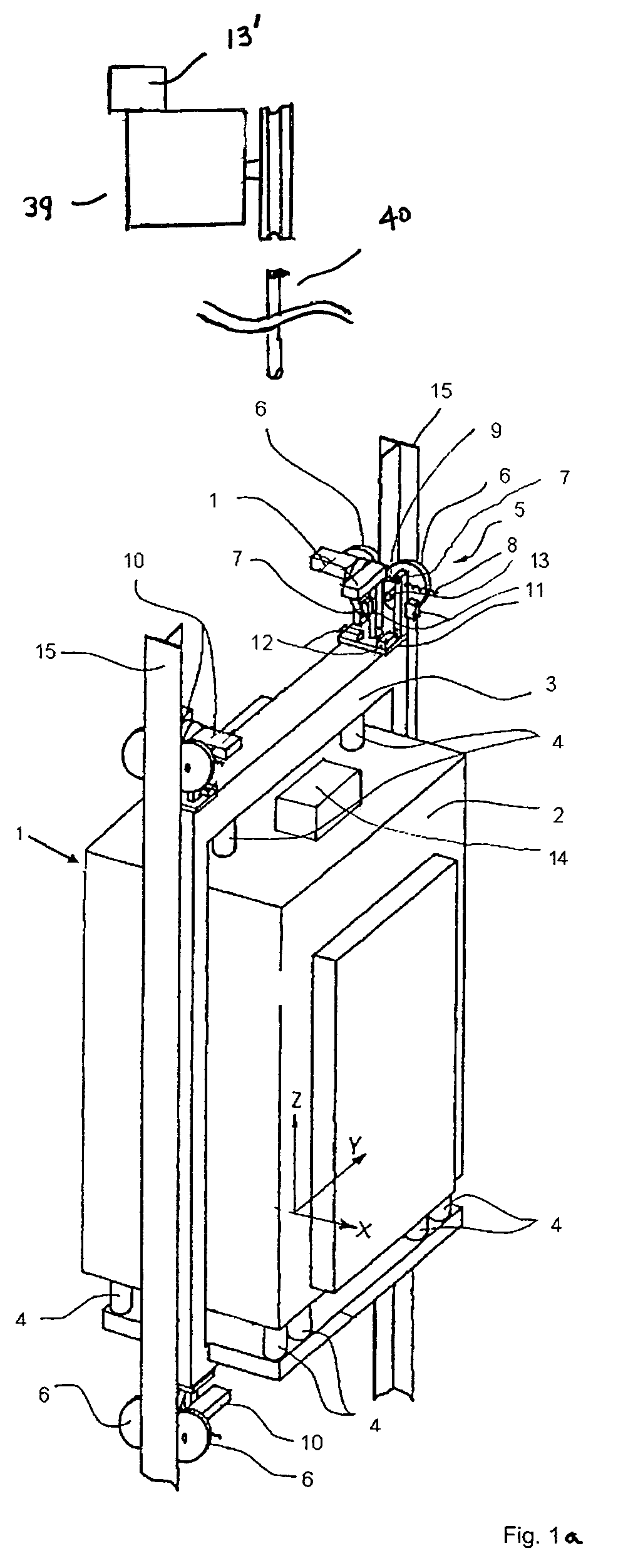
[0016]Before the regulating equipment according to the invention is explained in more detail, the realization of an overall system for active damping of vibrations or oscillations of a lift cage will initially be discussed with reference to FIG. 1.

[0017]The cage illustrated in FIG. 1 and provided generally with the reference numeral 1 is divided into a cage body 2 and a cage frame 3. The cage body 2 is mounted in the frame 3 with the help of several rubber springs 4 which are provided for insulation of solid-borne sound. These rubber springs 4 are designed to be comparatively stiff in order to suppress the occurrence of low-frequency vibrations.

[0018]The cage 1 is guided, with the help of four roller guides 5, at the two guide rails 15 which are arranged in a lift shaft (not shown). The four roller guides 5 are usually of identical construction and are mounted laterally at the bottom and the top at the cage frame 3. They each have a respective post on which are mounted three guide r...


PUM


Abstract

Equipment for reducing vibrations of a lift cage guided at rails comprises a plurality of guide elements for guiding the lift cage along the rails, a sensor for detecting positional changes of the lift cage and / or of accelerations occurring at the lift cage, an actuator arranged between the lift cage and the guide elements and a regulating device which, on the basis of the values transmitted by the sensor, controls the actuator for changing the position of the cage relative to the rails. The regulating device has an amplification which is variable in dependence on the vertical speed of the lift cage. The amplification of the regulating device is continuously raised after activation of the regulating device and continuously lowered after switching-off of the regulating device.

Description

[0001]The present invention relates to equipment for reducing or damping vibrations of a lift cage guided at rails and to a corresponding method for vibration damping.BACKGROUND OF THE INVENTION [0002]During travel of a lift cage in a lift shaft, different forces can act on the cage, which consists of the cage body and a cage frame holding the cage body, and excite the system to vibrate. The causes of vibrations in that case can be, in particular, unevennesses in the guide rails and forces produced by the slipstream about the cage. Beyond that, lateral traction forces transmitted by the traction cables or sudden positional changes of the load during travel can produce transverse vibrations.[0003]In order to increase travel comfort for persons using the lift, regulating systems are employed which are designed for the purpose of providing compensation for forces acting on the lift cage. For example, a system is known from U.S. Pat. No. 5,896,949 which comprises several guide elements ...

Claims


Application Information

Patent Timeline
Patent Type & Authority Patents(United States)
IPC IPC(8): B66B1/34B66B1/18B66B1/06B66B1/28B66B3/00B66B5/00B66B7/02B66B7/04B66B11/08
CPCB66B7/046B66B7/04
Inventor HUSMANN, JOSEFCORTONA, ELENA
Owner INVENTIO AG
Learn More