
Optical shutter for plasma display panel and driving method thereof

a technology of optical shutter and display panel, which is applied in the direction of identification means, instruments, static indicating devices, etc., can solve the problems of weak discharge, deformation of contrast, and loss of clearness

Inactive Publication Date: 2008-01-01
LG ELECTRONICS INC
View PDF2 Cites 3 Cited by
  • Summary
  • Abstract
  • Description
  • Claims
  • Application Information

AI Technical Summary

Benefits of technology

The present invention provides an optical shutter for a plasma display panel that prevents weak discharge during the non-display period and enhances the picture quality by improving contrast. The optical shutter includes a first transparent substrate with a first electrode pattern and a dielectric layer having a hydrophobic property surface, barrier ribs formed on the dielectric layer for separating operating regions, and a second transparent substrate with a second electrode pattern. The optical shutter is driven by applying voltages to the electrodes and can be formed using a black organic solution that moves according to the electrowetting phenomenon. The method of driving the optical shutter includes allowing the organic solution to block light emitted from the panel during the non-display period and applying voltages with a different polarity to the electrodes of the optical shutter during the display period.

Problems solved by technology

However, actually, since cells of the whole panel region are initialized during the reset and address periods, a weak discharge is generated.
This makes contrast degraded because the weak discharge is generated in the non-display period where the screen is not displayed actually.
Accordingly, there are problems in that the clearness decreases and the display quality is degraded accordingly.

Method used


Image

  • Optical shutter for plasma display panel and driving method thereof
  • Optical shutter for plasma display panel and driving method thereof
  • Optical shutter for plasma display panel and driving method thereof

Examples


Embodiment Construction

[0035]Preferred embodiments of the present invention will be described in a more detailed manner with reference to the drawings.

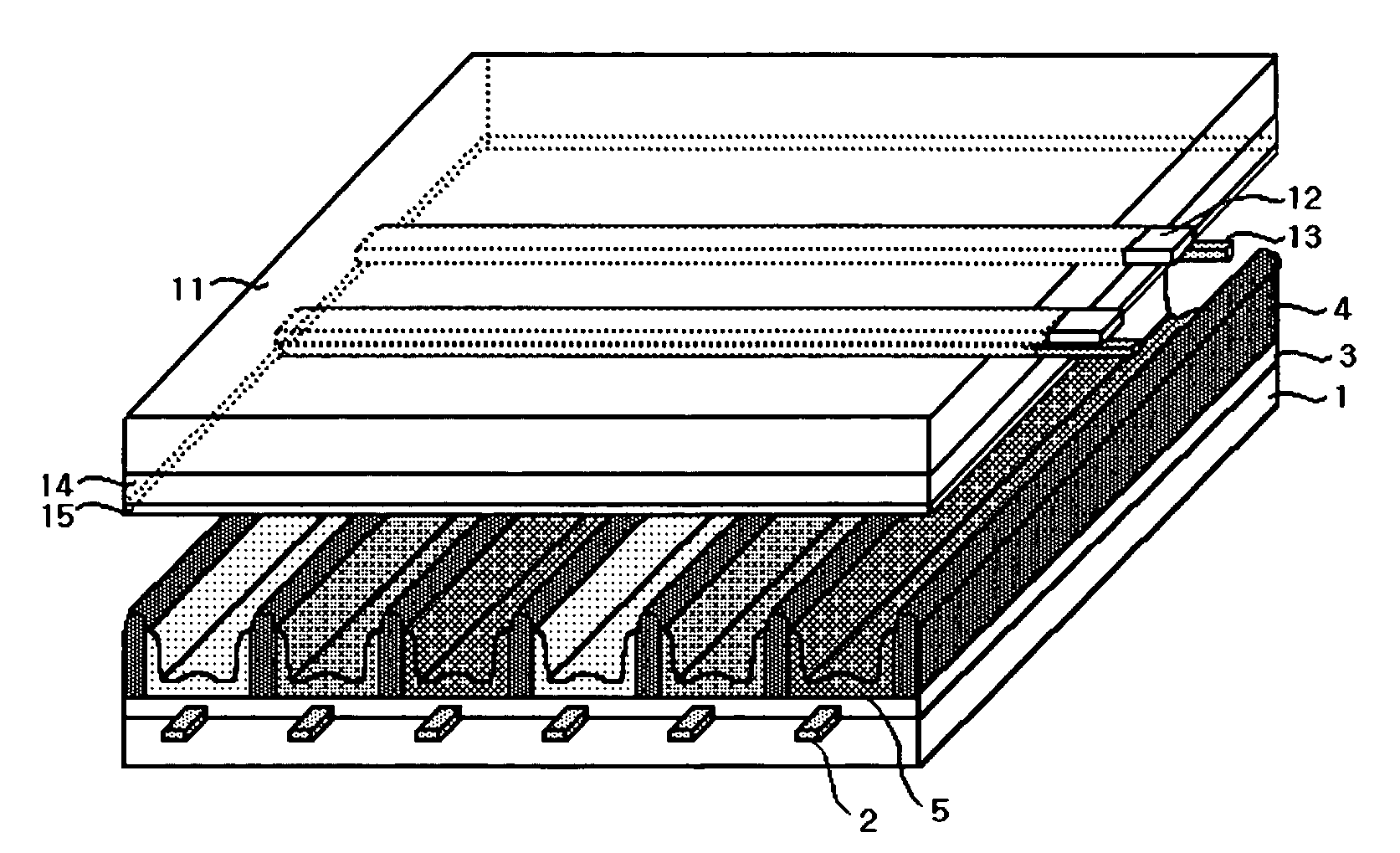
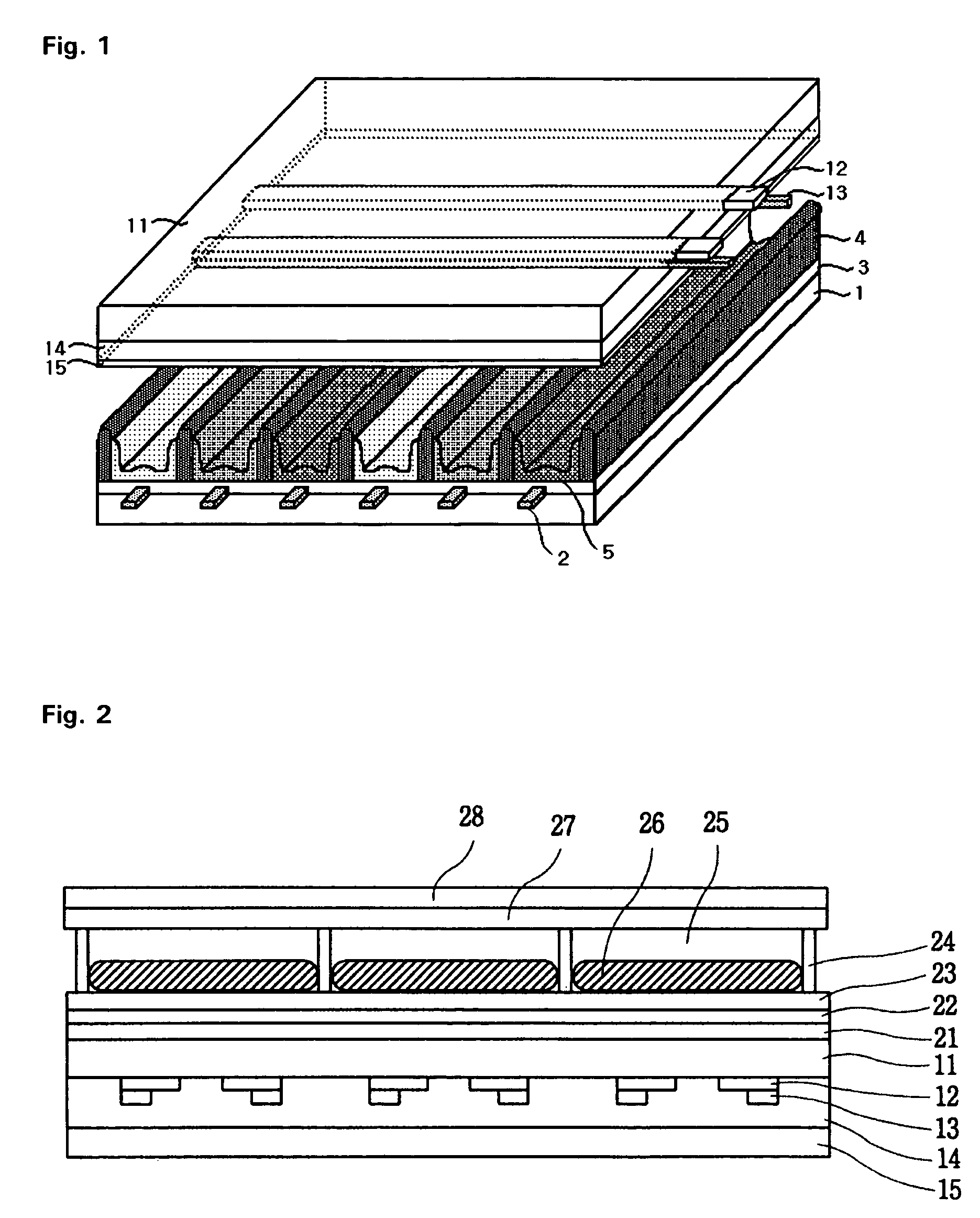
[0036]FIG. 2 is a plan view illustrating the plasma display panel to which the optical shutter according to an embodiment of the present invention is applied.

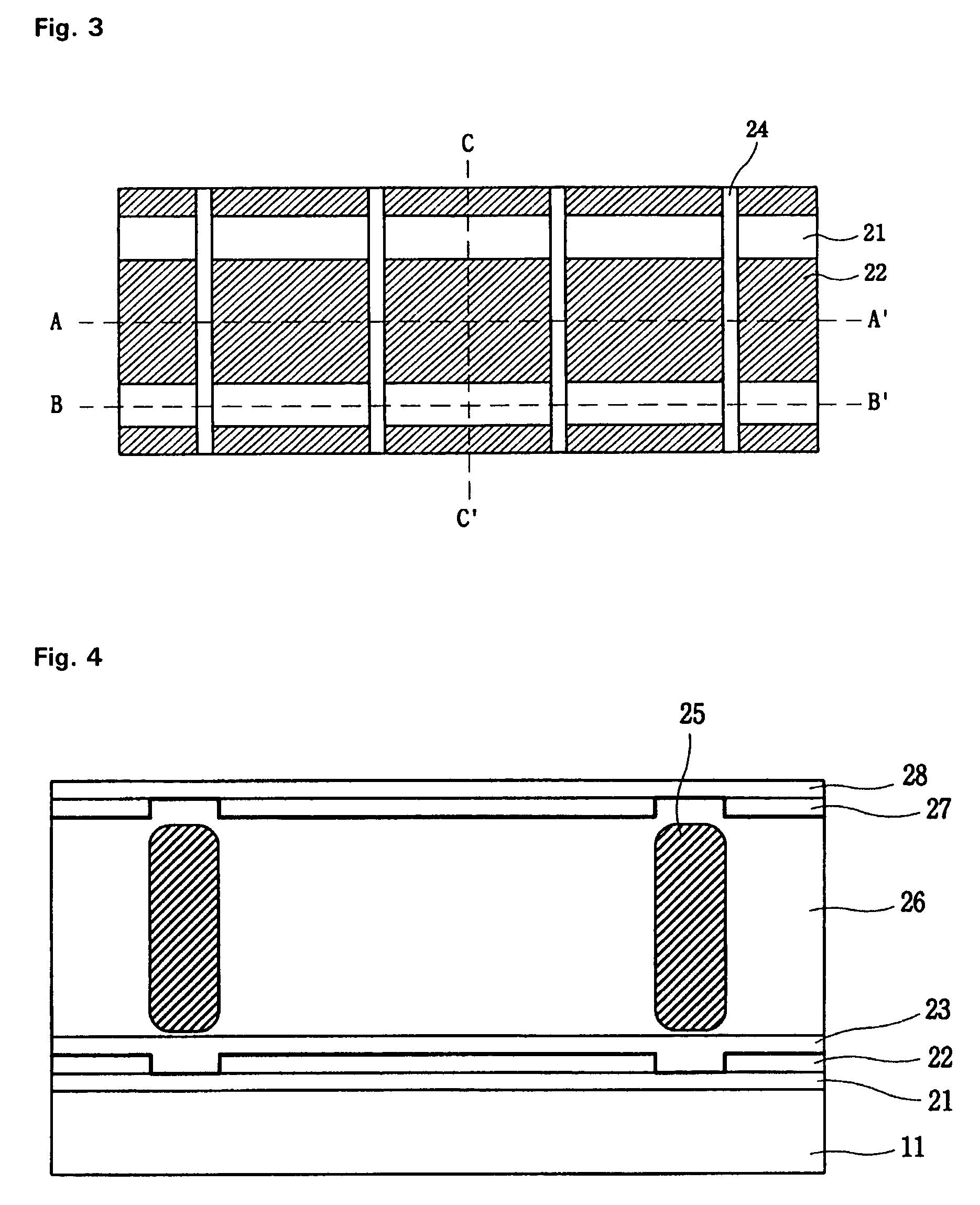
[0037]The construction of the optical shutter formed on an upper substrate 11 will be described with reference to FIG. 2. The optical shutter includes barrier ribs 24 for defining operating regions and physically supporting components, which are disposed between a first substrate 21 having a first electrode 22 and a dielectric layer 23 having a hydrophobic property surface, and a second substrate 28 having a second electrode 27. An aqueous solution 26 and an organic solution 25 are injected into the regions between the barrier ribs 24. The optical shutter is thus completed. The organic solution 25, which blocks the front display surface, is a material through which light cannot transmit. The organic so...


PUM

PropertyMeasurementUnit
thicknessaaaaaaaaaa
thicknessaaaaaaaaaa
sizeaaaaaaaaaa

Abstract

Disclosed herein are an optical shutter for a plasma display panel and driving method thereof. According to the present invention, an optical shutter, which employs a black organic solution that moves according to the electrowetting phenomenon and a pair of electrodes for providing voltages, is disposed on a display surface of the plasma display panel. In this state, during the non-display period, voltages are not applied to the optical shutter so that light emitted from the panel cannot transmit the optical shutter. During the display period, voltages having a different polarity are applied to the electrodes of the optical shutter so that light emitted from the panel can transmit the optical shutter. It is thus possible to completely prevent weak emission generating during the non-display period where cells are initialized and selected. Accordingly, there are effects in that contrast can be improved and the picture quality can be thus enhanced.

Description

CROSS-REFERENCES TO RELATED APPLICATIONS[0001]This Nonprovisional application claims priority under 35 U.S.C. § 119(a) on Patent Application No. 10-2003-0089830 filed in Korea on Dec. 10, 2003, the entire contents of which are hereby incorporated by reference.BACKGROUND OF THE INVENTION[0002]1. Field of the Invention[0003]The present invention relates to an optical shutter for a plasma display panel and driving method thereof. More particularly, the present invention relates to an optical shutter for a plasma display panel in which the optical shutter that can be selectively driven according to the electrowetting phenomenon is formed on a light-emitting unit of the plasma display panel, and the optical shutter is opened only during a display period, whereby contrast is improved, and a driving method thereof.[0004]2. Background of the Related Art[0005]Recently, the size of a plasma display panel (hereinafter, referred to as ‘PDP’) being a large-screen digital wall mount type televisi...

Claims


Application Information

Patent Timeline
Patent Type & Authority Patents(United States)
IPC IPC(8): G02B26/02G02F1/17G09F9/00G09F9/37G09G3/20G09G3/22G09G3/28G09G3/288G09G3/291G09G3/292G09G3/293G09G3/294G09G3/298H01J11/44H01J29/89
CPCG02B26/005H01J11/34H01J11/36H01J11/38
Inventor MOON, WON SEOK
Owner LG ELECTRONICS INC
Learn More