Zoom lens including four lens groups

a zoom lens and lens group technology, applied in the field of zoom lenses, can solve the problems of difficult to shorten the overall length of the lens system and difficult to make the entire image pickup device thinner, and achieve the effect of thinning the image pickup devi

Inactive Publication Date: 2008-01-01
FUJI PHOTO OPTICAL CO LTD
View PDF9 Cites 66 Cited by
  • Summary
  • Abstract
  • Description
  • Claims
  • Application Information

AI Technical Summary

Benefits of technology

[0018]The zoom lens of the present invention is suitable for being mounted and used in small equipment having an image pickup capability, such as PDAs (Personal Digital Assistants), video cameras, digital still cameras, and similar imaging devices and includes, in order from the object side along the optical axis Z1, a first lens group 10 of positive refractive power and having a reflecting member with a reflecting surface for folding the optical axis at least approximately ninety degrees, a second lens group 20 having negative refractive power, a third lens group 30 having positive refractive power and having a stop St on its image side, and a fourth lens group 40 having positive refractive power. As shown in FIG. 1, a right-angle prism G2 in the first lens group 10 serves as the reflecting member having a reflecting surface for folding the optical axis at least approximately ninety degrees. By providing the reflecting surface within the first lens group 10 having refractive elements and properly constructing the various lens groups, a thin construction can be made.

Problems solved by technology

On the other hand, the larger the number of lens elements in the lens system, the more easily the recent requirements for a larger number of pixels and higher performance of the image pickup element may be satisfied, making it difficult to shorten the overall length of the lens system, and, in turn, making it difficult to make the entire image pickup device thinner.

Method used


Image

  • Zoom lens including four lens groups
  • Zoom lens including four lens groups
  • Zoom lens including four lens groups

Examples


embodiment 1

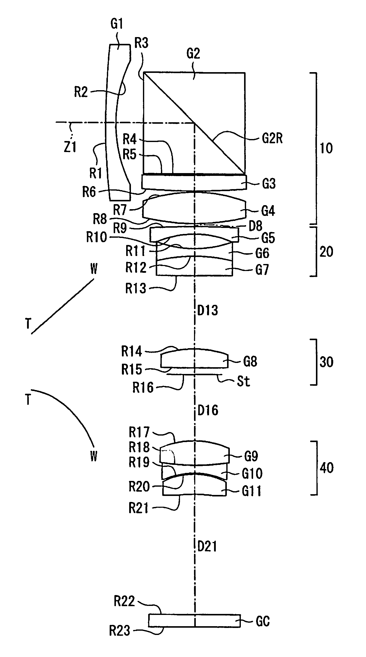
[0038]FIG. 1 shows a cross-sectional view of the zoom lens of Embodiment 1 at the wide-angle end. Table 1 below lists the group number (or GC, as appropriate), the surface number # in order from the object side, the radius of curvature R (in mm) of each surface on the optical axis, the on-axis surface spacing D (in mm) except that the on-axis surface spacings that vary with zooming are listed in Table 3 below, as well as the refractive index Nd and the Abbe number vd at the d-line (587.6 nm) of each optical element of Embodiment 1. Note that although R is the on-axis radius of curvature, for convenience of illustration, in FIG. 1 the lead lines from the R reference symbols extend to the surfaces being referenced but do not extend to the on-axis positions. Listed in the bottom portion of Table 1 are the focal length f (in mm) and the f-number FNO at the wide-angle and telephoto ends, and the maximum field angle 2ω at the wide-angle end and at the telephoto end for Embodiment 1.

[0039]...

embodiment 2

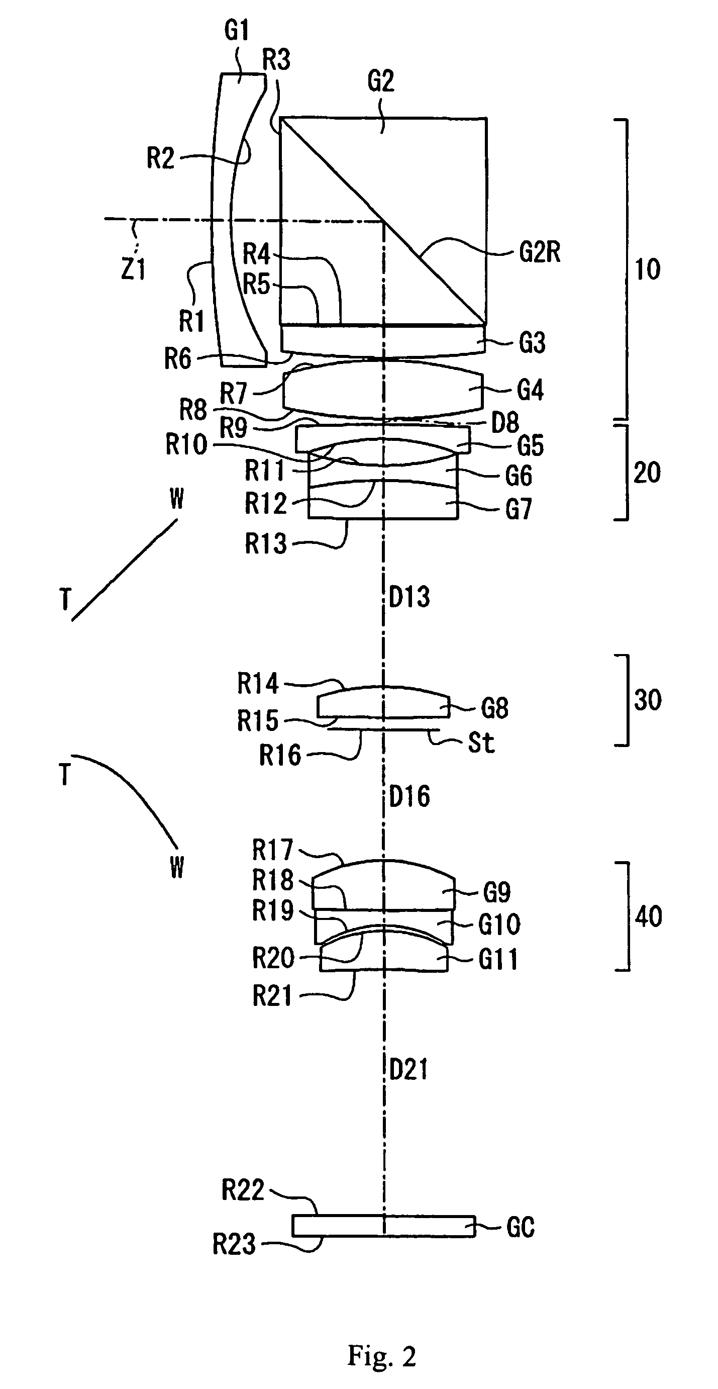
[0054]FIG. 2 shows a cross-sectional view of the zoom lens of Embodiment 2 at the wide-angle end. Embodiment 2 is similar to Embodiment 1 and therefore only the differences between Embodiment 2 and Embodiment 1 will be explained. Embodiment 2 differs from Embodiment 1 in its lens element configuration by having different radii of curvature of the lens surfaces, different aspheric coefficients of the aspheric lens surfaces, different optical element surface spacings, and some different refractive indexes and Abbe numbers.

[0055]Table 5 below lists the group number (or GC, as appropriate), the surface number # in order from the object side, the radius of curvature R (in mm) of each surface on the optical axis, the on-axis surface spacing D (in mm) except that the on-axis surface spacings that vary with zooming are listed in Table 7 below, as well as the refractive index Nd and the Abbe number vd at the d-line (587.6 nm) of each optical element for Embodiment 2. Note that although R is ...


PUM


Abstract

A zoom lens that is designed to enable a thinner image pickup device includes, in order from the object side, a first lens group having positive refractive power and a reflecting surface for folding the optical axis of the zoom lens approximately ninety degrees, a second lens group having negative refractive power, a third lens group having positive refractive power with a stop at its image side, and a fourth lens group having positive refractive power. The second lens group and the fourth lens group move along the optical axis during zooming, and the fourth lens group moves along the optical axis during focusing. The four lens groups have particular constructions and the zoom lens satisfies specified conditions related to the focal lengths of specified lens groups, the focal length of the zoom lens at the telephoto end, and the Abbe number of a specified lens element.

Description

TECHNICAL FIELD OF THE INVENTION[0001]The present invention relates to a zoom lens suitable for use in small equipment having an image pickup capability, such as PDAs (personal digital assistants), video cameras, and digital still cameras (commonly referred to as digital cameras), and similar devices.BACKGROUND OF THE INVENTION[0002]Image pickup elements, such as CCDs (Charge Coupled Devices) and CMOSs (Complementary Metal Oxide Semiconductors), have been used in digital still cameras and similar imaging devices with image pickup elements that are extremely miniaturized. This miniaturization, along with the light weight that this miniaturization supports, has been accompanied by a demand that the main body of the image pickup devices and the lenses mounted in these devices and used for imaging be similarly miniaturized and made light weight.[0003]In recent years, image pickup elements having a large number of pixels have been developed in order to achieve high image quality, and len...

Claims


Application Information

Patent Timeline
Patent Type & Authority Patents(United States)
IPC IPC(8): G02B15/14G02B17/00
CPCG02B15/173G02B5/04G02B15/144113
Inventor SATO, KENICHI
Owner FUJI PHOTO OPTICAL CO LTD
Why Eureka
Try Eureka