Device for purifying the exhaust gases of diesel engines

a technology for purifying devices and diesel engines, which is applied in the direction of machines/engines, electrical control, separation processes, etc., can solve the problems of large noise generation to a degree offensive to the ears, and the resistance to exhaust gas discharging in the diesel engine so as to affect the operation of the engine to a serious degr

Active Publication Date: 2008-01-08
ISUZU MOTORS LTD
View PDF19 Cites 21 Cited by
  • Summary
  • Abstract
  • Description
  • Claims
  • Application Information

AI Technical Summary

Benefits of technology

[0021]If the forced regeneration such as the post-injection is conducted by closing the exhaust throttle valve, the exhaust gas of a high pressure is accumulated on the upstream side. The above noise is produced by the impulsive pressure waves that is generated due to the instantaneously pressure drop of the accumulated exhaust gas to near the atmospheric pressure, when the exhaust throttle valve opens and the exhaust gas flows into the exhaust pipe on the downstream. The device for the purifying such as the continuously regenerating DPF has a large sectional area as compared to that of the exhaust pipe, and permits accumulating the exhaust gas of a large volume herein to produce noise of a further increased level. It is therefore a purpose of the present invention to decrease the noise at the time when the exhaust throttle valve is returned back to the fully opened state, in a diesel engine which is equipped with the continuously regenerating DPF and the exhaust throttle valve in combination.
[0022]In view of this purpose, the present invention has an object of decreasing the noise at the time when the exhaust throttle valve is returned back to the fully opened state after the forced regeneration of the continuously regenerating DPF has been finished. And the present invention provides an system, in which, when the forced regeneration is finished, the engine is operated at a decreased rotational speed and, thereafter, the exhaust throttle valve is fully opened.
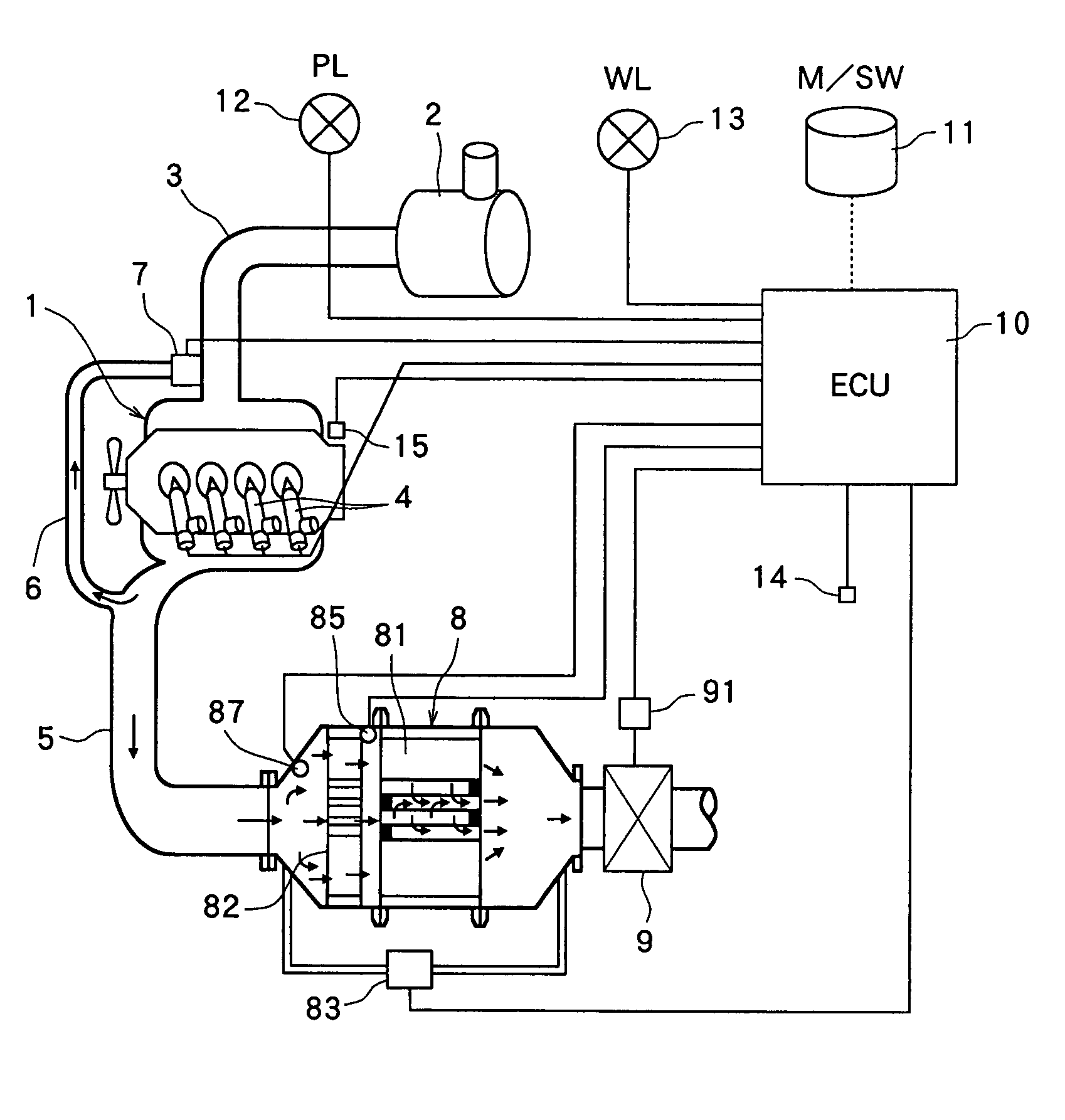
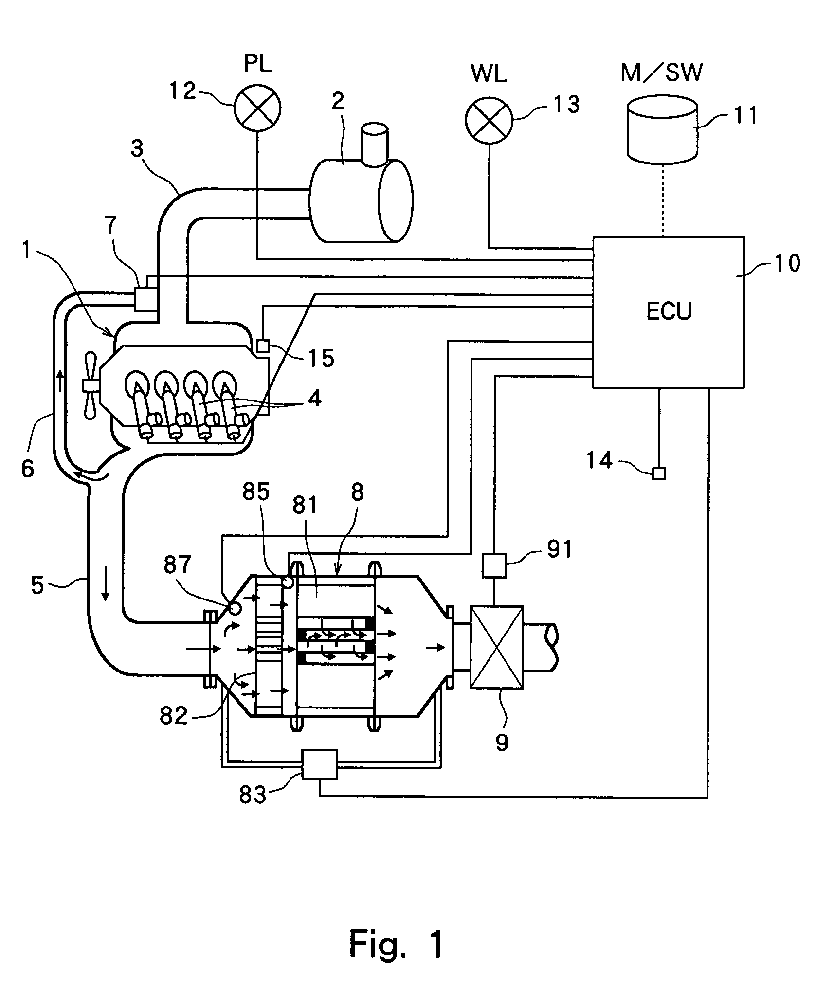
[0027]Even the continuously regenerating DPF having a catalyst on the upstream of the DPF, often makes it necessary to carry out forced regeneration of the DPF due to a decrease in the catalytic activity caused by a drop in the temperature of the exhaust gas. The DPF can be forcibly regenerated most effectively if the exhaust throttle valve is used in combination.
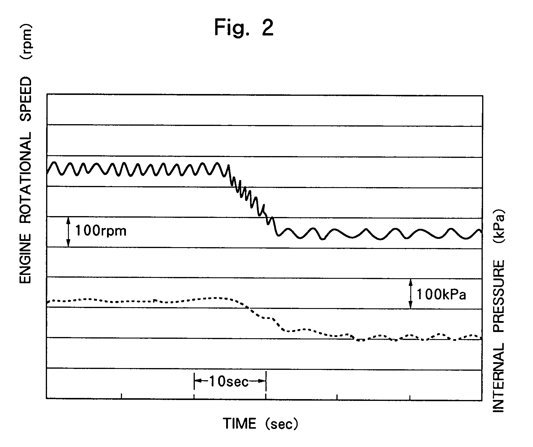
[0028]The system of the present invention effectively decreases the noise that generates at the time of returning the exhaust throttle valve back to its fully opened state, the exhaust throttle valve which is opened to a small degree during the diesel engine has been operated for forced regeneration. That is, in the present invention, when the particulate matter has deposited on the DPF in amounts greater than a predetermined amount and when the DPF is forcibly regenerated by opening the exhaust throttle valve to a small degree, the diesel engine, after the completion of the regeneration, is operated at a rotational speed lower than the engine rotational speed of during the regeneration and, thereafter, the exhaust throttle valve is opened to a large degree and is returned back to the fully opened state. When the rotational speed of the engine is lowered prior to opening the exhaust throttle valve, the flow rate of the exhaust gas and the pressure decrease and, hence, the pressure decreases in the continuously regenerating DPF. Therefore, the noise that generates at the opening of the exhaust throttle valve is greatly decreased as compared to that of the prior art which does not conduct the operation at a decreased rotational speed. Besides, the noise can be decreased without adding any particular devices.
[0030]During the continuously regenerating DPF provided in the exhaust system of the diesel engine is regenerated in a state where the exhaust throttle valve is opened to a small degree, an increased load is exerted on the engine to seriously affect the driving of the vehicle. If the regeneration is executed by bringing the vehicle into a halt and by operating the diesel engine in idling condition as described in claim 2, it is allowed to avoid the disadvantageous effect upon operating the vehicle. As described in claim 3, further, the rotational speed can be easily controlled in a stable operating state if the diesel engine is operated by the feedback control with the idling rotational speed as a target value in regenerating the continuously regenerating DPF and the target value is lowered after the completion of the regeneration.
[0033]Here, the amount of formation of the particulate matter and the amount of its deposition on the DPF vary depending upon the operating conditions of the vehicle, and difficulty is involved in determining the necessity for the forced regeneration. As described in claim 6, therefore, it is desired that an alarm device is provided to let the driver know the fact that the particulate matter has deposited in amounts greater than a predetermined amount on the diesel particulate filter. This enables the driver to reliably judge the necessity for executing the forced regeneration and to take a suitable countermeasure.

Problems solved by technology

Here, however, if the exhaust throttle valve provided in the exhaust pipe is squeezed at the time of forced regeneration of the DPF, the resistance to exhaust gas discharging in the diesel engine so increases as to affect the operation thereof to a serious degree.
It is, however, found that when the exhaust throttle valve provided downstream of the continuously regenerating DPF is quickly returned back to the fully opened state, a large noise generates to a degree which is offensive to the ears.

Method used


Image

  • Device for purifying the exhaust gases of diesel engines
  • Device for purifying the exhaust gases of diesel engines
  • Device for purifying the exhaust gases of diesel engines

Examples


Embodiment Construction

[0039]Hereinafter, the device for purifying the exhaust gases of a diesel engine according to the present invention will be described with reference to the drawings. FIG. 1 is a drawing schematically illustrating a device for purifying the exhaust gases of a diesel engine according to the present invention, wherein those corresponding to the parts and components of the prior art (FIG. 5) are denoted by the same reference numerals. FIG. 2 is a graph illustrating a change n the diesel engine rotational speed and a change in the internal pressure in the continuously regenerating DPF during the control operation is executed according to the present invention.

[0040]The fundamental elements constituting the device for purifying the exhaust gases of the diesel engine of the present invention and the method of its operation are not particularly different from those of the conventional device illustrated in FIG. 5. Namely, in the cylinder of the diesel engine body 1, the fuel injected from t...


PUM

PropertyMeasurementUnit
temperatureaaaaaaaaaa
activating temperatureaaaaaaaaaa
A-weighted sound pressure levelaaaaaaaaaa

Abstract

In a diesel engine provided with a diesel particulate filter 81 and an exhaust throttle valve 9, noise is decreased that is produced when the exhaust throttle valve is returned back to the fully opened state after a diesel particulate filter 81 has been regenerated by oxidizing and removing the particulate matter deposited thereon. The exhaust system of the diesel engine is equipped with the diesel particulate filter 81 and a catalyst 82 on the upstream thereof, and is further equipped with the exhaust throttle valve 9 on the downstream. The diesel particulate filter 81 is regenerated by operating the diesel engine in a state where the exhaust throttle valve 9 is opened to a small degree. When the regeneration has finished, the diesel engine is run at a decreased rotational speed and, thereafter, the exhaust throttle valve 9 is returned back to the fully opened state. When the engine is run at a decreased rotational speed, the pressure in the exhaust system decreases making it possible to greatly decrease the noise that generates at the time of the opening of the exhaust throttle valve 9.

Description

BACKGROUND OF THE INVENTION[0001]1. Field of the Invention[0002]The present invention relates to a device for purifying the exhaust gases and a control unit therefor, which are provided in an exhaust system of an engine in order to remove pollution components contained in the exhaust gases emitted from a diesel engine and, particularly, to remove particulate matter which is to be reduced in connection with exhaust gas regulations.[0003]2. Description of the Related Art[0004]As an important way to protect the environment, regulations have now been legislated for reducing nitrogen oxides (NOx) and hydrocarbons (HC) which are pollution components contained in the exhaust gases emitted from the engines for vehicles, and a variety of technologies have been vigorously developed to reduce such pollution components. In particular, the regulations concerning the exhaust gases of diesel engines are becoming stringent in recent years, and it is expected that more strict regulations will be leg...

Claims


Application Information

Patent Timeline
Patent Type & Authority Patents(United States)
IPC IPC(8): F01N3/00F01N7/00F02D9/04B01D46/42B01D53/94F01N3/02F01N3/023F01N3/025F01N3/029F01N3/035F02D41/02F02D41/08F02D41/16F02D41/38F02D41/40F02D45/00
CPCF01N3/0235F02D9/04F02D41/029F02D41/08F02D41/405
Inventor ARATSUKA, YOSHITAKAHASHIMOTO, HIROFUMINISHI, TAKUO
Owner ISUZU MOTORS LTD
Why Eureka
Try Eureka