Diecasting machine

a diecasting machine and casting technology, applied in the field of diecasting machines, can solve the problems of potential risk of oil smear, and achieve the effects of high injection speed, high speed, and high injection speed

Active Publication Date: 2008-01-08
TOYO MACH & METAL CO LTD
View PDF3 Cites 0 Cited by
  • Summary
  • Abstract
  • Description
  • Claims
  • Application Information

AI Technical Summary

Benefits of technology

[0010]In a diecasting machine equipped with an electric servomotor as a drive source for advancing or retracting an injection plunger, it is not a boosted (in other words, raised) pressure but a high injection speed in a high-speed injection step that can be hardly achieved only by the output of the electric servomotor. In the construction having the electric servomotor as a primary drive force for the injection plunger and also the hydraulic drive force as an auxiliary drive source for driving the injection plunger in an advancing direction, the present invention makes it possible to release the power of the hydraulic drive source at once and hence, to advance the injection plunger at high speed. Therefore, a high injection speed can be surely achieved with good responsibility. Further, the injection and filling of molten metal in the mold can be surely conducted in short time, so that castings can be obtained with high quality.

Problems solved by technology

Hydraulic diecasting machines, however, involve the potential risk of smear with oil or the like.

Method used


Image

  • Diecasting machine
  • Diecasting machine
  • Diecasting machine

Examples


Embodiment Construction

[0018]The diecasting machine according to the embodiment of the present invention will hereinafter be described with reference to the accompanying drawings.

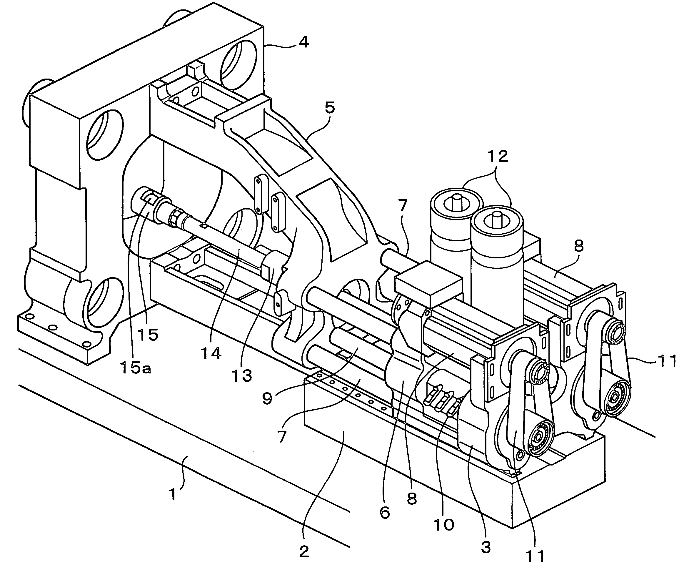
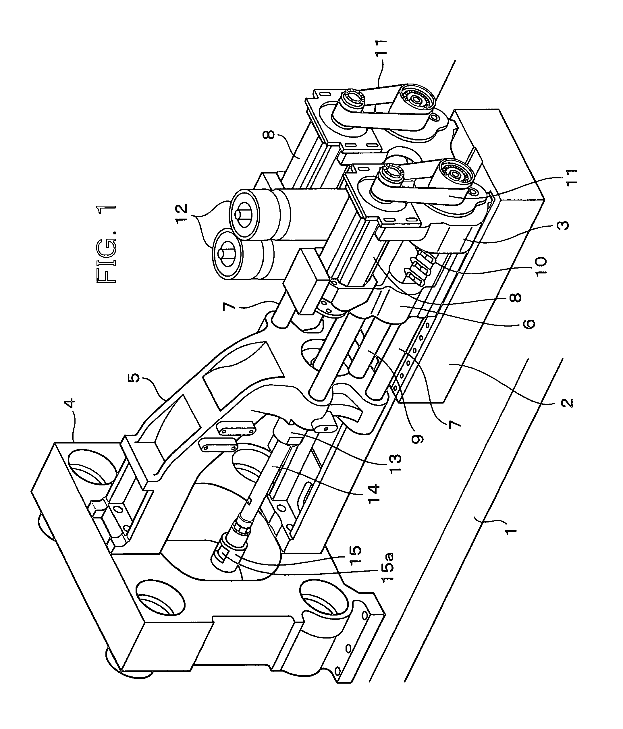
[0019]FIG. 1 shows a main base 1; a base member 2 for the injection mechanism as mounted on the main base 1; a holding block 3 arranged on the base member 2; a stationary die plate 4 arranged on the main base 1; a support member 5 held on the stationary die plate 4, etc.; a movable member 6 arranged movably forward or rearward on the base member 2; plural guide bars 7 arranged extending between the holding block 3 and the support member 5 to guide an advancement or retraction of the movable member 6; a pair of electric servomotors 8 arranged for injection on the holding block 3; a pair of ball screws 9 rotatably held on the holding block 3 such that rotations of the corresponding electric servomotors 8 can be transmitted to them via rotation transmitting systems 11 constructed of pulleys and belts, respectively; nut members 10 co...


PUM

PropertyMeasurementUnit
speedaaaaaaaaaa
diameteraaaaaaaaaa
diameteraaaaaaaaaa

Abstract

A diecasting machine is provided with a mold and an injection plunger to inject and fill molten metal in the mold by an advancement of the injection plunger. The diecasting machine includes an electric servomotor and a hydraulic drive source. The electric servomotor is usable as a first drive source capable of driving the injection plunger at an advancing speed lower than 1 m / sec, while the hydraulic drive source is usable as a second drive source capable of driving the injection plunger at an advancing speed not lower than 1 m / sec.

Description

FIELD OF THE INVENTION[0001]This invention relates to a diecasting machine of the type that molten metal is injected and filled in a mold by an advancement of an injection plunger.DESCRIPTION OF THE BACKGROUND[0002]There are widely known diecasting machines of the type that a molten metal material is injected and filled in a cavity of a mold to obtain a product. With such a diecasting machine, a metal material (for example, Al alloy, Mg alloy or the like) which has been molten in a smelting furnace is metered and lifted out by a ladle upon every shot, and the thus-ladled molten metal (molten metal material) is poured into an injection sleeve and is then injected and filled in a cavity of a mold by an advancement of an injection plunger.[0003]An injection step which is performed by such a diecasting machine generally consists of a low-speed injection step and a high-speed injection step, and in the high-speed injection step, it is necessary to inject and fill molten metal in a mold a...

Claims


Application Information

Patent Timeline
Patent Type & Authority Patents(United States)
IPC IPC(8): B22D17/10
CPCB22D17/10B22D17/2015
Inventor TANIGUCHI, YOSHIYA
Owner TOYO MACH & METAL CO LTD
Why Eureka
Try Eureka