Spring-armed kitchen utensils and locking mechanism therefor

a technology for kitchen utensils and springs, which is applied in the field of spring-armed kitchen utensils, can solve the problems of excessive space occupied by drawers, inability to store these kinds of utensils, and the functional ends of utensils can also get caught on other things, so as to facilitate gripping

Inactive Publication Date: 2008-01-08
GOURMET SETTINGS
View PDF11 Cites 25 Cited by
  • Summary
  • Abstract
  • Description
  • Claims
  • Application Information

AI Technical Summary

Benefits of technology

[0017]Likewise, various shapes and utensil types are possible, bearing the present locking mechanism. The utensil may include a handle portion on each arm proximate to the attachment ends. That is, the arms may have a specially designated portion for gripping (either made out of a different material, or specially shaped to facilitate gripping).
[0018]Various configurations of functio

Problems solved by technology

It is awkward to store these kinds of utensils when not in use.
The arm span when sprung open takes up excessive space in a drawer.
The functional ends of the utensils can also get caught on other things, particularly if the ends have any projecting or sharp edges.
While relatively simple, the loop lock is not ideal, since it can be inadvertently engaged by gravity while the utensil is in active use.
The loop lock can also be inadvertently released at un

Method used


Image

  • Spring-armed kitchen utensils and locking mechanism therefor
  • Spring-armed kitchen utensils and locking mechanism therefor
  • Spring-armed kitchen utensils and locking mechanism therefor

Examples


Embodiment Construction

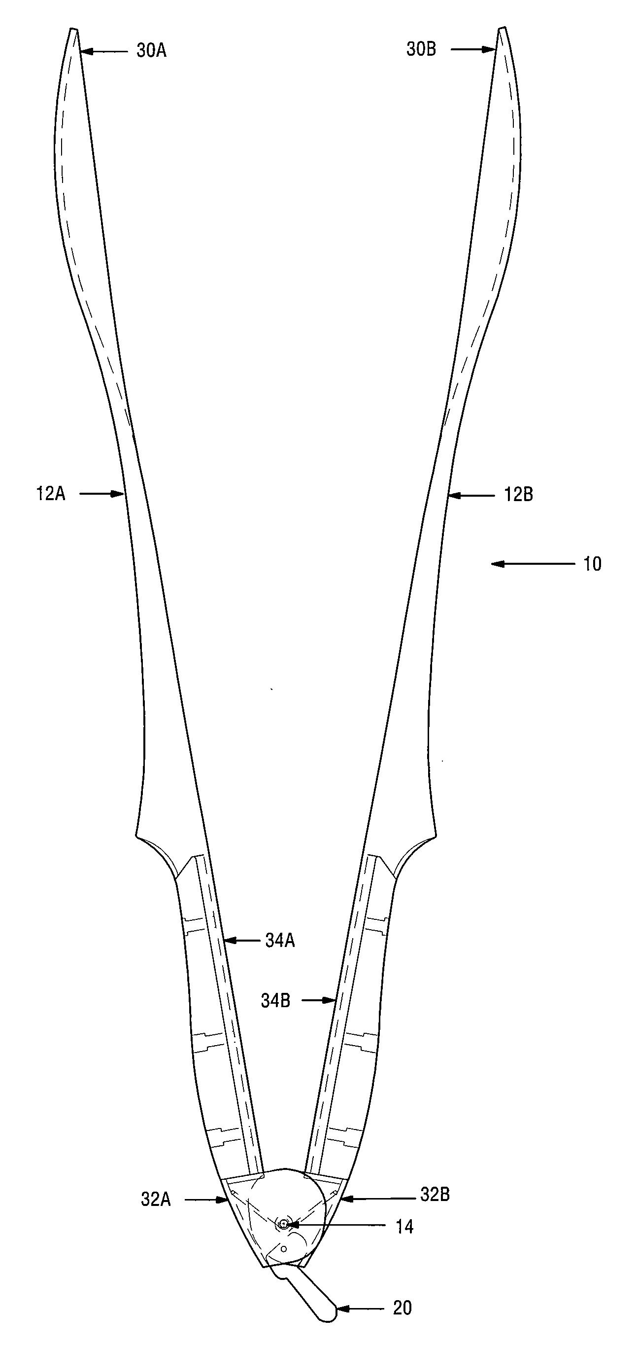
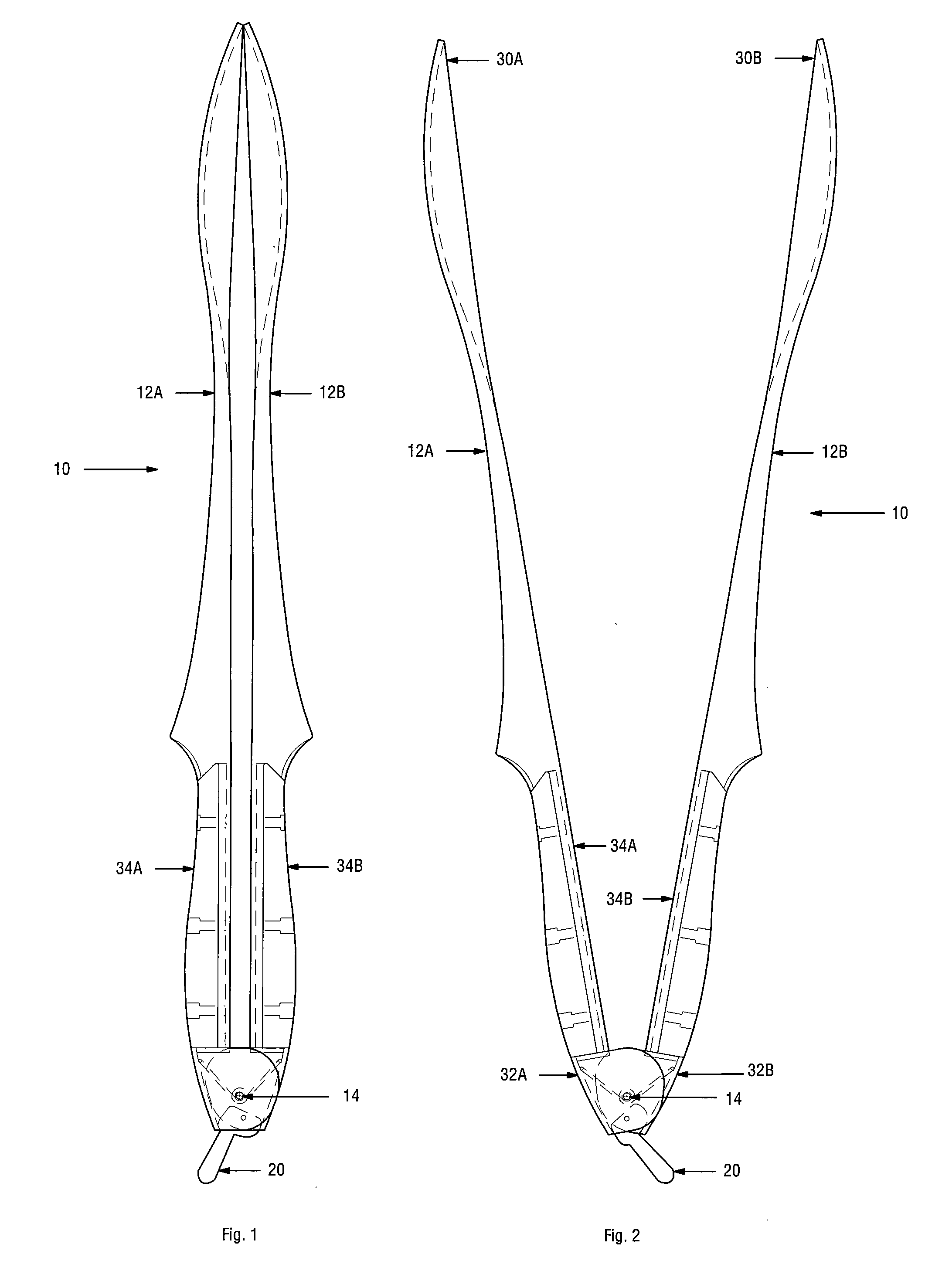
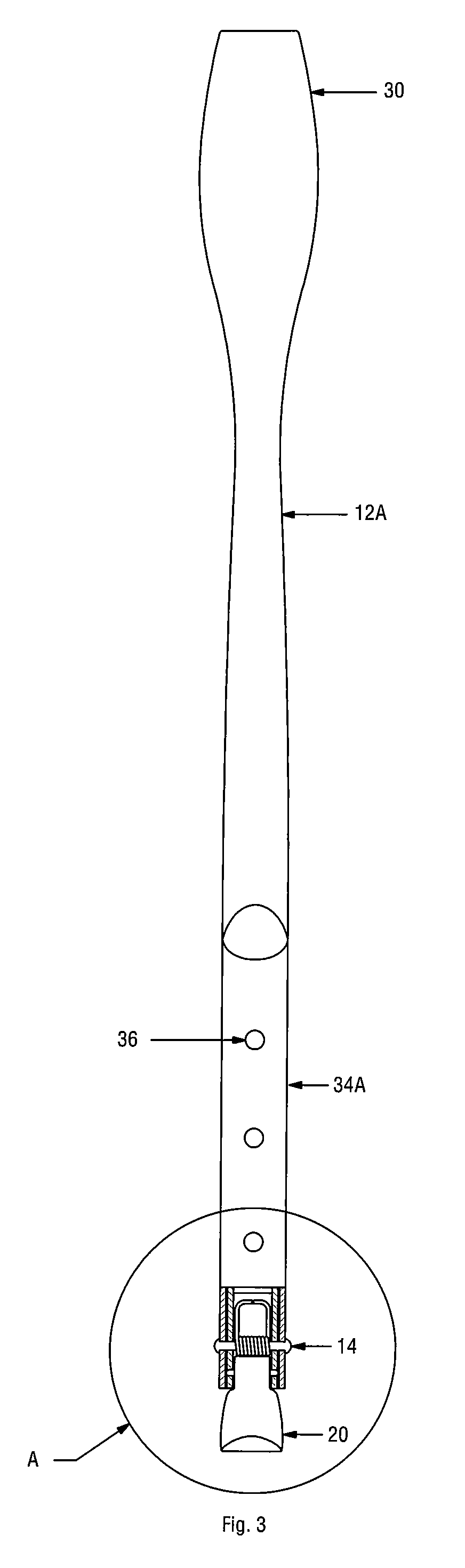
[0030]A locking utensil is provided, as shown in the Figures. FIGS. 1-8 show a locking tongs 10, according to an embodiment of the invention. A preferred embodiment of the invention is for barbecue tongs. However, various types of locking utensils are contemplated, and the invention is not limited to the tongs shown in the drawings.

[0031]Tongs 10 have a pair of arms 12A, 12B. Arms 12A, 12B have forward functional ends 30A, 30B and rear attachment ends 32A, 32B. Preferably, the arms are nested together at their attachment ends 32A, 32B, such as by overlapping flanges. The attachment ends 32A, 32B are pivotably joined at a main pivot 14. The nested attachment ends 32A, 32B define a channel between them, as can be seen in FIG. 4.

[0032]A spring, disposed in the channel, is used to bias the arms into open position (as shown in FIGS. 2, 6, 8) except when arms 12A, 12B are manually brought (squeezed) together for gripping an item or when locked (as shown in FIGS. 1, 5, 7). The spring may b...


PUM


Abstract

A locking utensil is provided. The utensil has a pair of pivoting spring-loaded arms each having a forward functional end and a rear attachment end. The utensil includes a locking assembly, featuring an eccentrically shaped cam disposed in a channel between the arms. One side of the cam has a projecting shoulder dimensioned to frictionally engage an inside surface of the channel when the shoulder side of the cam is rocked into contact with the inside surface. The cam can releasably retain the arms closed to lock them. An actuator tab that extends out of the channel is used to rock the cam into and out of locking engagement.

Description

BACKGROUND OF THE INVENTION[0001]1. Field of the Invention[0002]The invention relates to spring-armed kitchen utensils.[0003]2. Description of the Related Art[0004]Spring-armed utensils are commonly used in kitchens for gripping or preparing food items. Examples include spring-armed tongs, garlic presses, cherry pitters, and other types of utensils.[0005]It is awkward to store these kinds of utensils when not in use. The arm span when sprung open takes up excessive space in a drawer. The functional ends of the utensils can also get caught on other things, particularly if the ends have any projecting or sharp edges.[0006]Various types of locking mechanisms have been provided, the simplest of which is a loop or ring, which encircles the arms and which can be slid toward the functional ends of the arms when pinched together to retain the arms in closed position. While relatively simple, the loop lock is not ideal, since it can be inadvertently engaged by gravity while the utensil is in...

Claims


Application Information

Patent Timeline
IPC IPC(8): A47G21/10A47J43/28
CPCA47G21/10A47J43/283A47J19/06A47J23/00
Inventor KERR, HELEN
Owner GOURMET SETTINGS
Why Eureka
Try Eureka