Harmonic propulsion and harmonic controller
Inactive Publication Date: 2008-01-08
THE TRUSTEES OF COLUMBIA UNIV IN THE CITY OF NEW YORK
View PDF20 Cites 46 Cited by
Summary
Abstract
Description
Claims
Application Information
AI Technical Summary
This helps you quickly interpret patents by identifying the three key elements:
Problems solved by technology
Method used
Benefits of technology
[0011]According to one aspect of the invention, vibratory motion is used to perform the functions of devices described herein, namely, to move along a level surface, to climb up a smooth vertical or slanted wall, to move upside down on a ceiling, or to climb up a hollow tube. Another aspect of the invention comprises a solution to the problem of controlling the direction of such moving devices. Without directional control, the utility of a moving device is much reduced; and, with directional control, the method and device for which is taught by the present invention, it becomes possible to build devices which can be used for exploration of intricate spaces, under either remote control or control based on an on-board set of sensors and decision-making circuits. A device according to the invention is expected to be have various applications. One potential use is in the in the medical field, for example, in or with a partly or wholly self-propelled endoscope or other invasive medical device.
[0012]A great advantage of vibratory or harmonic propulsion is that such devices may be very small and simple compared to more conventional devices, such as wheeled devices. This is because this form of propulsion does not require axles, bearings, transmissions, or even wheels, as are needed for wheeled devices. This form of propulsion does not require propellers or jet engines. The present invention requires a system with a source of vibrations and a driving surface, which comes in contact with the surface upon which the device is moving.
[0013]Also, unlike wheels or treads (as in a tank), harmonic propulsion can be effected on any or all surfaces of the device, instead of being limited to the aspects of the device (the driving surface of the wheels or treads). Therefore, it becomes very easy using harmonic propulsion to build devices which can, for example, ascend the inside of hollow pipes since the device can obtain propulsion from the entire circumference of the pipe. Also, the surface of vibration can be adjusted as to its stiffness and texture so that the device can move on a great variety of terrain (for example, hard, smooth, dry ground versus softer wet ground). In one embodiment, it is envisioned that this technology will allow for the development of a practical self-propelled endoscope to explore a patient's gastrointestinal tract or another corporeal channel or site.
Problems solved by technology
Also, unlike wheels or treads (as in a tank), harmonic propulsion can be effected on any or all surfaces of the device, instead of being limited to the aspects of the device (the driving surface of the wheels or treads).
Method used
Image
Click on the blue label to locate the original text in one second.
Reading with bidirectional positioning of images and text.
Examples
example 1
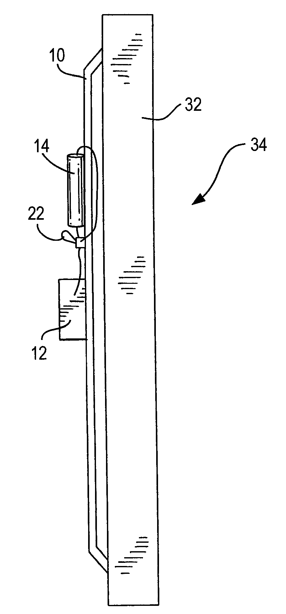
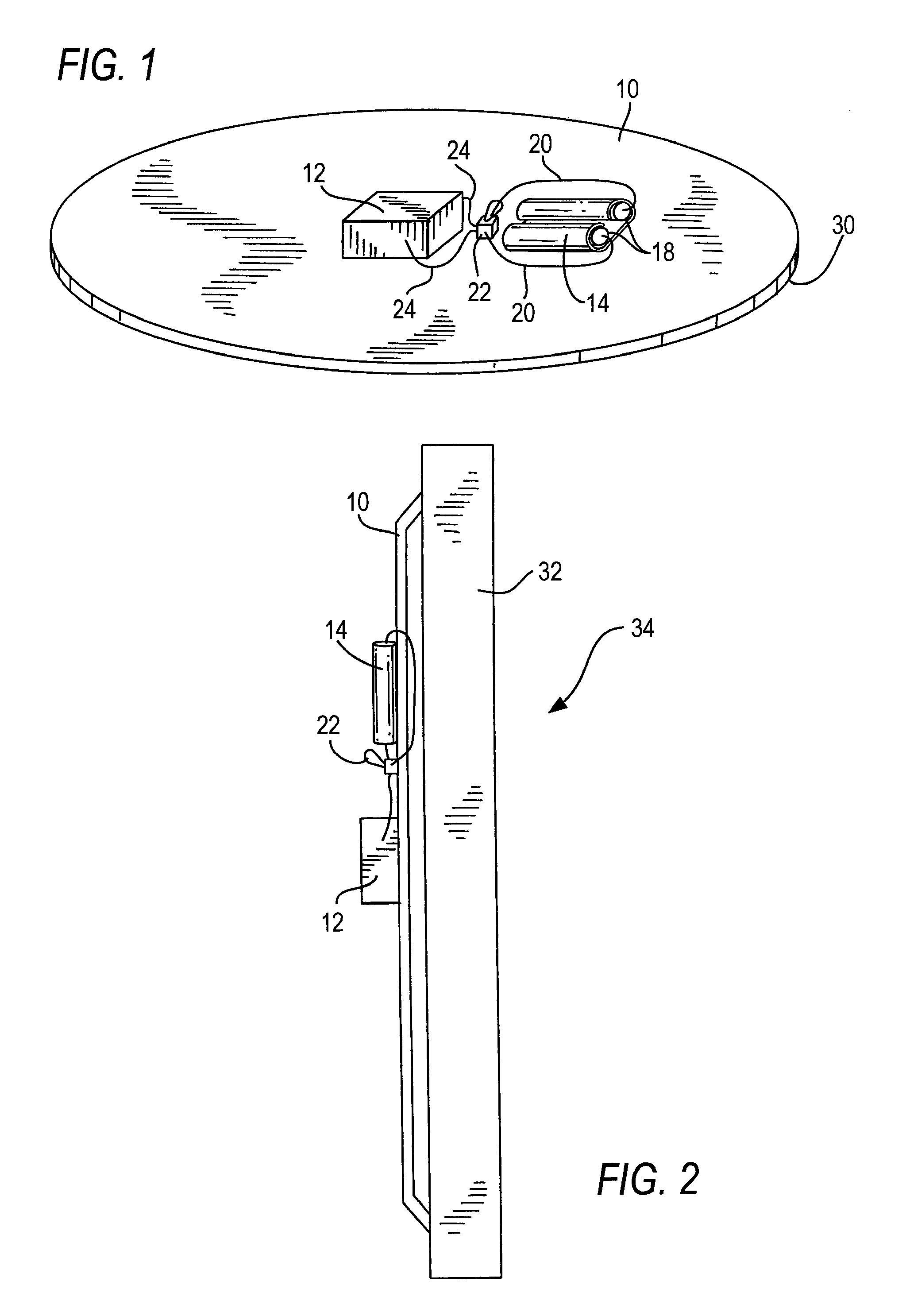
[0063]The device comprises a Styrofoam pie plate (9 inches in diameter, of central depth ¾ inch, with an edge at the circumference of width approximately one-half inch), an electrical motor with an eccentric weight, and 2 Ni—Cd batteries (AAA size). The motor and batteries are placed on the underside of the pie plate.
[0064]In one use, the device, with the pie plate upside down, translated with the circumferential edge in contact with a surface. This device translated in a vertical direction along a wall, in an embodiment termed “wall crawling pie plate.”
[0065]In another use, the motor and batteries can be placed in an enclosure, such as a film can. The device, with the pie plate upside down, translated with the circumferential edge in contact with a surface. Specifically, the device can translate along a surface, such as a porcelain tub surface, underneath water.
example 2
[0066]The device comprises an approximately flat 3 inch diameter, approximately 1 mm thick, circle or approximate circle of material (which can be cut, for example, from the bottom of the 9″ diameter Styrofoam pie plate), a pager motor, and a power source. The power source can be wires connected to the motor which lead to a battery remote from the 3 inch diameter circle.
[0067]On energizing the motor and creating vibrations, the device translated along a surface.
example 3
[0068]The device comprises a ping pong ball with a hole, a motor, and a power source. The motor and power source can be placed within the ping pong ball. On energizing the motor and creating vibrations, the device spins when placed in a cup of water. It is believed that this is through rotational traveling waves.
PUM
Abstract
A device and method for propelling objects using periodic or harmonic vibrations is described. The device comprises a flexible substrate or surface and a source of vibrational energy that is applied to the substrate or surface. Specific embodiments include a device which can move along a flat surface, which can climb a smooth vertical or slanted wall, which can move along a ceiling while suspended upside down, which can climb up a smooth hollow tube, or which can move through liquids.
Description
CROSS-REFERENCE TO RELATED APPLICATION[0001]This application is based upon co-pending, commonly assigned U.S. provisional patent application Ser. No. 60 / 507,667, filed Sep. 30, 2003, which is incorporated herein in its entirety.FIELD OF THE INVENTION[0002]The present invention generally relates to a method for moving objects. The present invention specifically is directed to propelling objects by using periodic or harmonic vibrations. Embodiments of the present invention include a method to move an object along a flat surface (translating horizontally), to move an object up a smooth vertical wall (climbing vertically), to move an object along a ceiling while the object is upside down relative to its position in normal horizontal translation, to climb inside a smooth hollow tube, to swim through liquids, and to rotate. The present invention is also directed to devices which execute the various movements.BACKGROUND OF THE INVENTION[0003]Historically, the usual means for propelling obj...
Claims
Application Information
Patent Timeline
Application Date:The date an application was filed.
Publication Date:The date a patent or application was officially published.
First Publication Date:The earliest publication date of a patent with the same application number.
Issue Date:Publication date of the patent grant document.
PCT Entry Date:The Entry date of PCT National Phase.
Estimated Expiry Date:The statutory expiry date of a patent right according to the Patent Law, and it is the longest term of protection that the patent right can achieve without the termination of the patent right due to other reasons(Term extension factor has been taken into account ).
Invalid Date:Actual expiry date is based on effective date or publication date of legal transaction data of invalid patent.