Footwear with integrated energy wave sockliner

a technology of energy wave and shoeliner, which is applied in the direction of uppers, bootlegs, stiffners, etc., can solve the problems of increasing discomfort, increasing impact force and potential discomfort of wearers, and design usually losing effectiveness, so as to improve the distribution of pressure and improve the comfort of shoes

Inactive Publication Date: 2013-12-05
BROWN SHOE
View PDF8 Cites 6 Cited by
  • Summary
  • Abstract
  • Description
  • Claims
  • Application Information

AI Technical Summary

Benefits of technology

[0007]Although the present invention will be described in connection with one embodiment of a typical shoe, it is likewise well-suited for use in essentially any type of shoe construction, including shoes having a midsole and / or shoe constructions having a high heel or no heel (flat) configuration. The present shoe assembly is designed to enable unhindered natural foot motion between the foot and the ground. To begin the design process, the shoe is constructed with a cupped heel, a contoured arch, a radiused forepart and neutral heel / forefoot position to create a foot bed that anatomically cradles a wearer's foot. An integrated sockliner / strobel insole is added, the sockliner / strobe insole including a plurality of grooves on its top face and it may optionally include a plurality of ridges and valleys on its bottom face. The integrated sockliner / strobel insole includes perimeter edges for attaching the sockliner / insole to the upper either by strobel stitching or cementing the upper edges under the perimeter of the sockliner / insole edges. The outsole is sculpted to have rounded natural edges and an anatomically correct flex location toward the forefoot of the shoe where softer, more flexible materials are used. The outsole is further designed with harder, protective materials strategically placed in high ground-contact areas to deliver protection and support. An optional midfoot support element (or support shank) may be positioned between the sockliner and outsole to control torsional stiffness. Upper materials are selected to minimize restriction of movement and promote breathability.
[0008]The integrated sockliner of the present invention further includes a raised area in the midfoot region and a recessed area located in the hind foot region. The sockliner is preferably comprised of a base foam, including, but not limited to, EVA, polyurethane (PU), blended co-polymers and the like. Sockliner hardness would preferably be in the range of about 25C to 70C on an Asker C scale. The midfoot support element is preferably made from a material including, but not limited to, molded plastic, rigid EVA, Texon / tuck board and the like, with a thickness of between about 1 mm and 3 mm, and with a hardness of between about 50A and 90A on a Shore A scale. Such a construction allows for: (a) increased contact between the foot and shoe interior; (b) a flexibility improvement such that less foot force is required to bend the shoe; (c) an improved gait by enabling natural motion during walking; (c) promoting more midfoot versus heel strike; (d) reduced weight over conventional shoes; and (e) increased foot stimulation through more utilization of bones, tendons and muscles during footstrike. The raised area is positioned to underlie the medial arch of the wearer's foot and the recessed area is positioned to underlie the heel of the wearer's foot. The recessed area is defined by the peripheral edges formed around the hind foot region from the medial side to the lateral side of the heel. The peripheral edge in the hind foot region forms a raised portion where it wraps around the heel of the wearer's foot.
[0009]The anatomically shaped and formed integrated sockliner has been designed to reflect the natural contours of the human foot. The sockliner of the present invention extends from the rear of the shoe forward, receiving the wearer's toes. The shaped plantar surface topography maximizes surface contact with the wearer's foot and increases comfort. The recessed area functions as an extended heel seat located in the distal portion of the sockliner, cradling the foot and bearing a majority of the weight while distributing pressure. A reduced heel center thickness is provided to avoid peak heel pressure during heel impact. The shape and outline of the sockliner reflects the natural contours of the human foot. As the foot is “loaded” with body weight during heel strike, the present sockliner compresses and expands within the shoe, supporting the foot and insuring maximum contact.
[0012]The optional ridge surfaces are positioned parallel and below the base plane, extending downwardly. The upward extension of the ridge surfaces forms the side walls of the ridges which are generally perpendicular to the base plane. The optional valley surfaces are positioned parallel and above the base plane, extending downwardly. The downward extension of the valley surfaces form the side walls of the valleys which are generally perpendicular to the base plane. On the bottom face, the ridge surfaces may come into direct or indirect contact with the upper surface of the outsole. The outsole is preferably constructed from rubber or polyurethane, in either single or dual compound areas. For example, a dual compound outsole may have high-traction compound at high ground-contact locations, and a wear-resistant compound toward the perimeter of the outsole. Preferably, the hardness of either or both of these compounds would be in the range of about 45A to 75A on a Shore A scale. Such configurations effectively lock in the anatomical shape within the shoe while providing cushioning and support to the wearer.
[0013]When a foot is inserted into a shoe that houses the present shoe assembly, the recessed area of the integrated sockliner serves to receive and locate the heel in a recessed area which is substantially concaved, and the raised area acts to support the medial arch of the wearer's foot so that the integrated sockliner substantially contacts the entire bottom surface of the wearer's foot. The combination of a raised area under the medial arch, a recessed area immediately under the heel, and the use of a sockliner material that substantially maintains its form, improves the distribution of the pressure and the comfort of shoes made in accordance with the teachings of the present invention. It is generally recognized that the integrated sockliner of the present invention is more resistant to “bottoming out,” which for purposes of this disclosure, means that the sockliner will not reach a threshold of force where the material comprising the sockliner will not further compress. As pressure is applied to the sockliner, the ridges compress vertically, causing them to expand horizontally. The valleys provide space for the ridges to expand horizontally, allowing for additional compression and cushioning.
[0014]In still another embodiment, the present shoe assembly includes an energy wave sockliner, a strobel insole, and an outsole. In this embodiment, the strobe insole is provided as a separate layer and is positioned between the energy wave sockliner and the outsole. Preferably, the top surface of the outsole is shaped to conform to the bottom surface of the strobel insole and may be constructed of a high resiliency foam such as, but not limited to, neoprene, polyurethane, SEBS, EBA, rubber and the like. The energy wave sockliner, the strobel insole, and the outsole may be secured to one another using any suitable attachment means. An optional midfoot support element may likewise be positioned between the strobel insole and the outsole to again control tortional stiffness toward the midfoot region.

Problems solved by technology

However, these designs usually lose their effectiveness over the course of a day, as they become increasingly compressed.
In some cases, prolonged use may result in increasing discomfort as the cushioning becomes less effective.
However, there are many problems with such “barefoot” running shoes, and their “fingers.” The lack of cushioning and protection underfoot, combined with encouragement to users that they land on their forefoot (rather than their heels) increases the impact force and potential discomfort experienced by the wearer.
Further, the radical design is a turn-off to many mainstream consumers, which limits the end use and wearing occasions.

Method used


Image

  • Footwear with integrated energy wave sockliner
  • Footwear with integrated energy wave sockliner
  • Footwear with integrated energy wave sockliner

Examples


Embodiment Construction

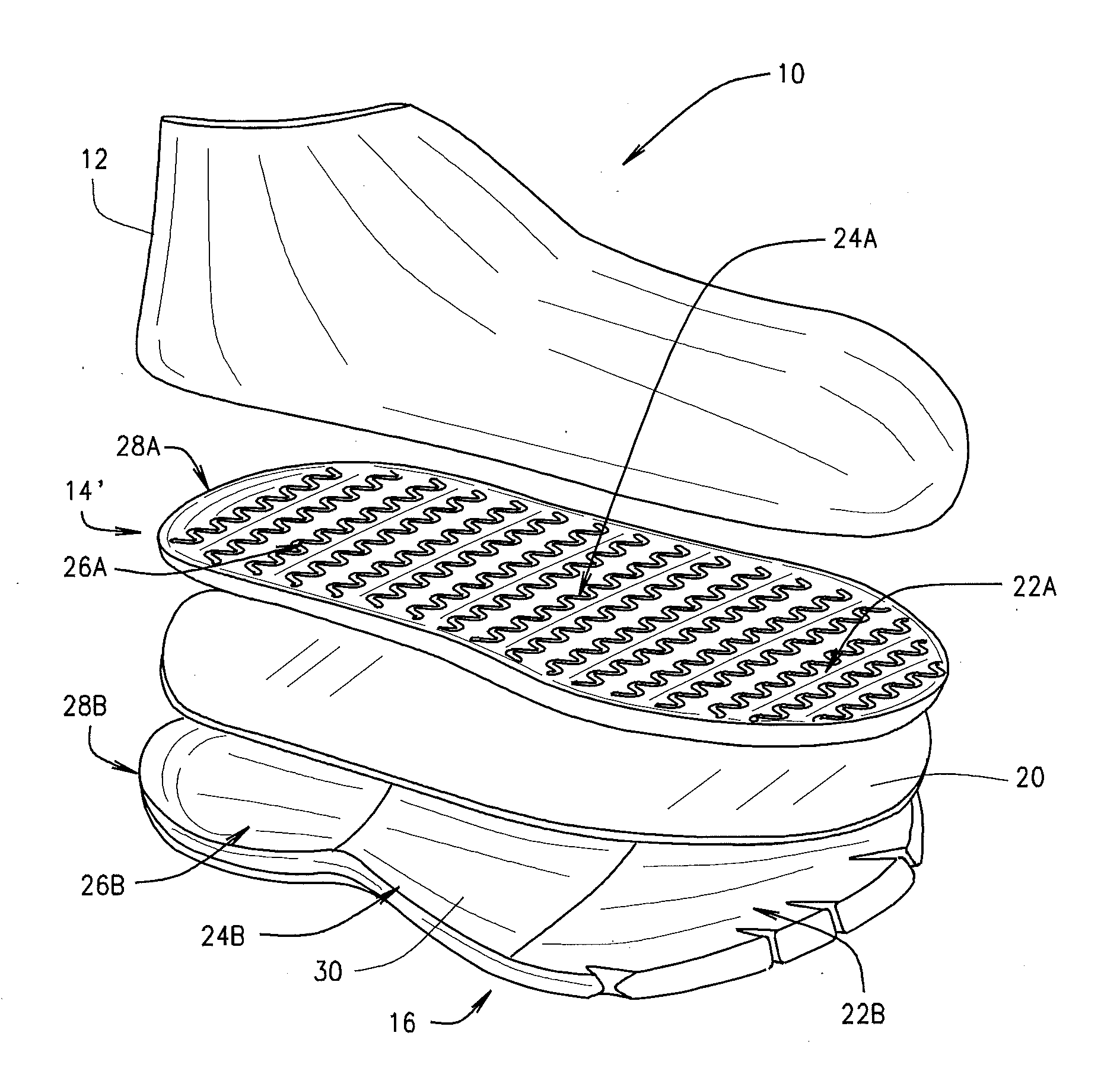
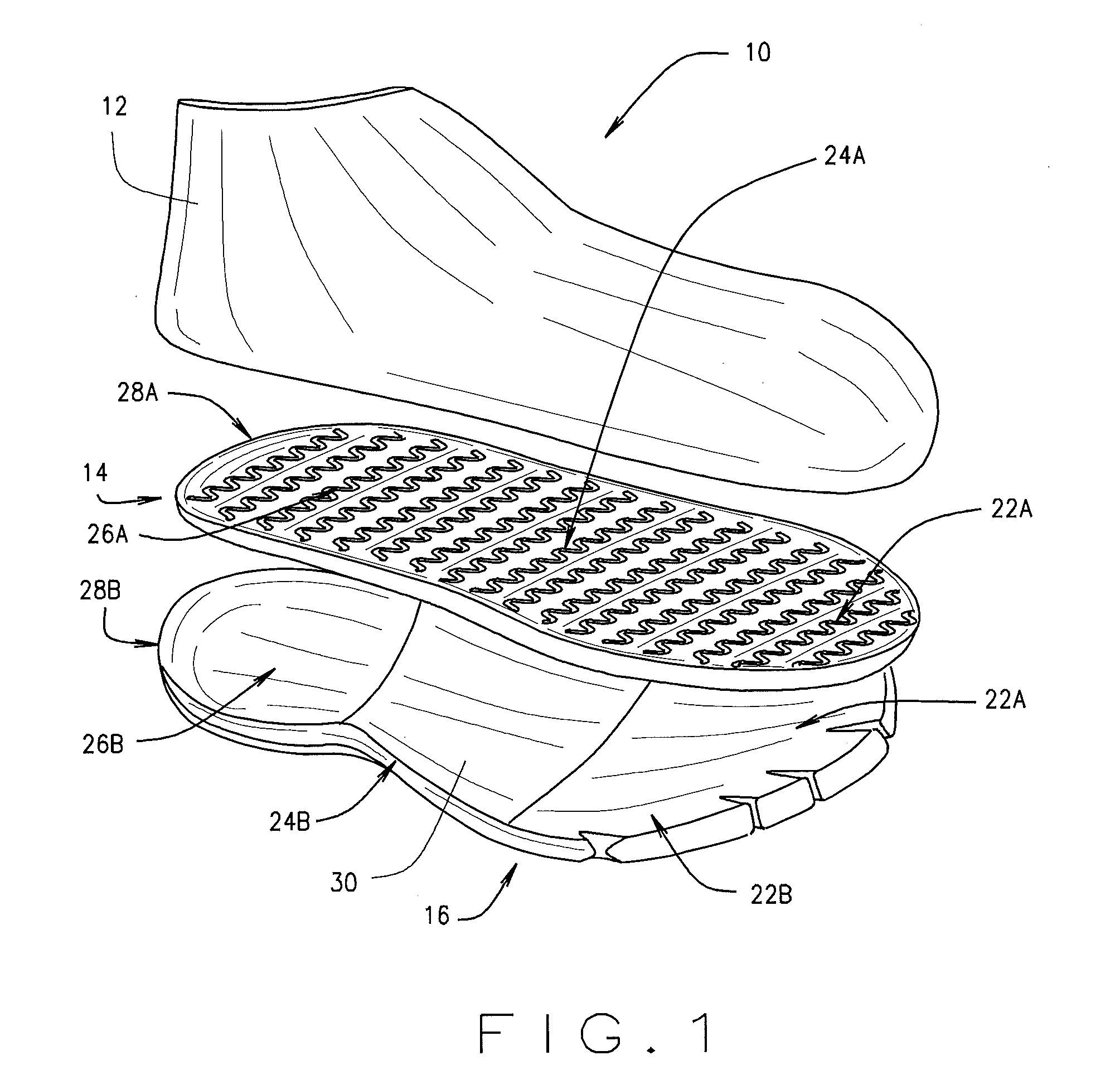
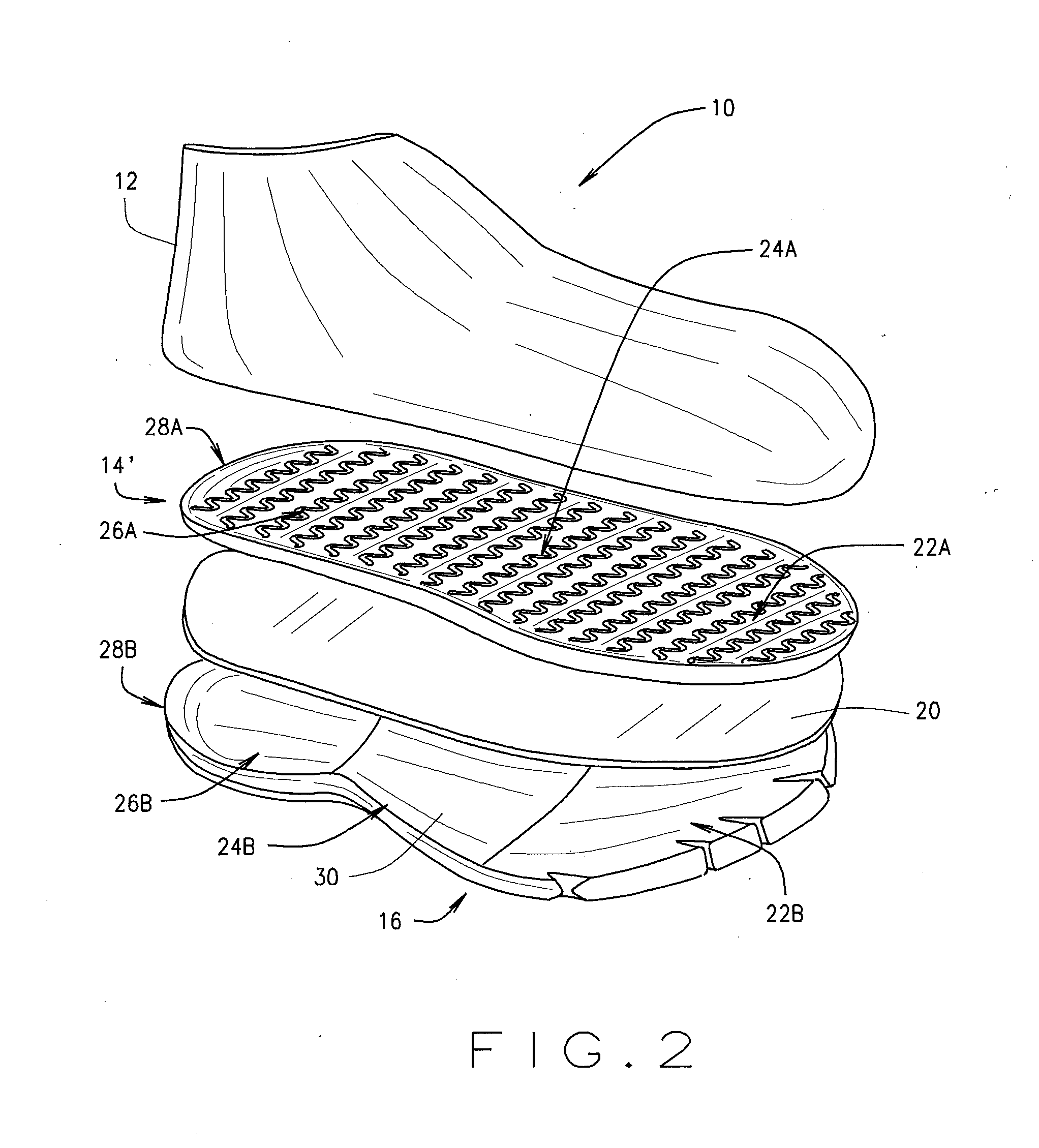
[0024]Referring now to the drawings, more particularly by reference numbers, FIG. 1 illustrates one embodiment of the shoe assembly 10 constructed in accordance with the teachings of the present invention. The present shoe assembly 10 is configured to provide improved comfort during running and other activities. The shoe assembly 10 includes an upper 12 that can be formed in any suitable style or shape, an integrated sockliner / strobel layer 14 and an outsole 16. The outsole 16 is positioned on the underside of the shoe for engagement with a walking surface such as the ground, sidewalk, floor or other supporting surface. Preferably, the top surface of the outsole 16 is shaped to conform to the bottom surface of the sockliner 14. The sockliner 14 and outsole 16 may be secured to one another using any suitable attachment means including, but not limited to, cement, adhesives, glue, welt, direct attachment constructions and the like.

[0025]For ease of reference herein, the human foot may...


PUM


Abstract

A shoe assembly is designed to enable unhindered natural foot motion between the foot and the ground. The shoe assembly includes an integrated anatomically shaped sockliner and outsole. The sockliner includes a top face and a bottom face, each having a generally planar surface, extending along a base plane. On the top face of the sockliner, a plurality of grooves extend across the base plane in a generally undulating pattern for engagement with the sole of the foot. The bottom face of the sockliner may include a plurality of alternating ridges and / or valleys extending from the inside to the outside of the foot in a generally undulating pattern for engagement with the outsole. A strobel insole of encapsulated high resiliency foam may be positioned between the sockliner and the outsole. An optional midfoot support element may be positioned between the insole and outsole to control tortional stiffness.

Description

CROSS-REFERENCE TO RELATED APPLICATIONS[0001]This non-provisional application is a continuation-in-part of U.S. patent application Ser. No. 13 / 484,379, titled FOOTWEAR PROMOTING NATURAL MOTION, filed May 31, 2012, and is a continuation-in-part of U.S. patent application Ser. No. 13 / 491,570, titled ENERGY WAVE SOCKLINER, filed Jun. 7, 2012. This application incorporates by reference all of the disclosures therein.BACKGROUND OF THE INVENTION[0002]The present invention relates generally to the construction of a shoe, and, more particularly, to a shoe assembly which provides improved comfort and which promotes a natural motion of the foot by simulating a barefoot experience, and by allowing better flexibility, improved ground contact and less weight.[0003]Shoes, at their most fundamental level, are intended to provide protection and comfort to the human foot during the course of day-to-day activities. Shoe designs have varied greatly over time as well as from culture to culture, with th...

Claims


Application Information

Patent Timeline
Patent Type & Authority Applications(United States)
IPC IPC(8): A43B13/18
CPCA43B7/141A43B7/142A43B7/144A43B23/22A43B13/12A43B13/187A43B13/40
Inventor VATTES, DAVID L.
Owner BROWN SHOE
Why Eureka
Try Eureka