Wearable antenna

a wearable antenna and loop antenna technology, applied in the direction of antennas, underwater equipment, antenna supports/mountings, etc., can solve the problems of wearers' adoption of low frequency radio communications and severe impede the movement of wearers, and achieve the effect of minimizing movement restriction and maximizing antenna transmission area

Inactive Publication Date: 2009-06-25
WFS TECH
View PDF3 Cites 11 Cited by
  • Summary
  • Abstract
  • Description
  • Claims
  • Application Information

AI Technical Summary

Benefits of technology

[0011]These and other objects of the present invention are provided in a wearable article configured to be worn by a person underwater or underground; An antenna. with at least one loop, is coupled to the wearable item. The antenna provides transmission or receipt of electromagnetic signals and has a size and geometry that maximizes antenna transmission area while minimizing a restriction on movement by the person wearing the wearable article. The antenna carries an alternating current that provides conductive attenuation and has three different field components. Each field component has a different geometric loss when moving a distance r from the antenna. R is a propagating distance from the antenna.

Problems solved by technology

It is beneficial to maximise the area enclosed by the loop but a physically large structure will severely impede a wearer's movement.
This limitation has been one of the factors restricting the adoption of low frequency radio communications by wearers.

Method used


Image

  • Wearable antenna
  • Wearable antenna
  • Wearable antenna

Examples


Embodiment Construction

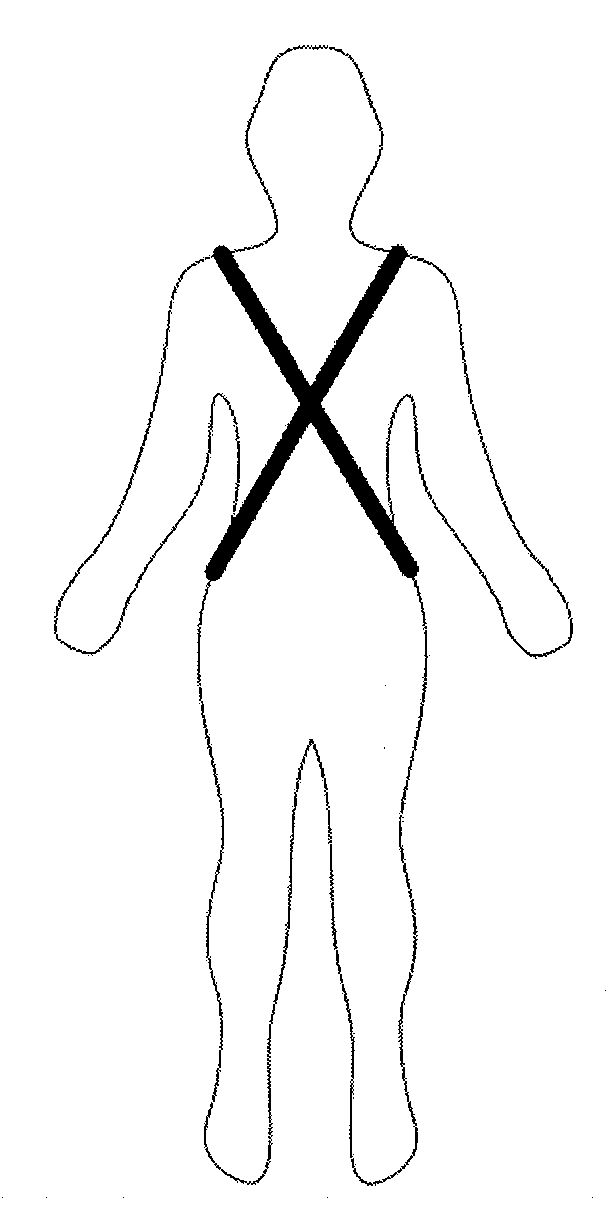
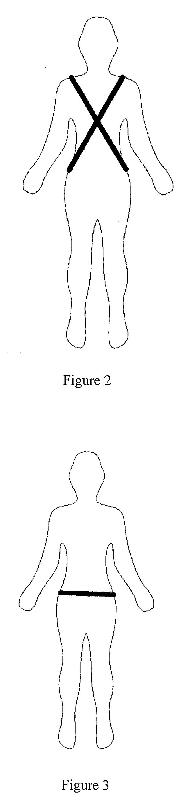
[0021]In one embodiment, the present invention provides a system of magnetic and / or magneto-inductive loop antennas for use by a person underwater or underground, including but not limited to a mobile wearer. The total loop area of the antenna can be maximised while the practical motion restriction imposed on the person due to body movement is reduced and or minimized by integrating the loop antennas within the wearer's clothing. This provides a mechanism of communication that has minimal dependence on orientation of the person under water or under ground. In various embodiments, geometries of the antennas can make use of crossed loop structures to achieve a more uniform antenna field pattern as more fully described hereafter.

[0022]The wearer's freedom of movement is an important operational requirement for several reasons: safety; need to minimise the chance of snagging on external structures which could trap the wearer below the water or underground; the ability to carry out inten...


PUM


Abstract

A wearable article of clothing and the like is configured to be worn by a person underwater or underground; An antenna. with at least one loop, is coupled to the wearable item. The antenna provides transmission or receipt of electromagnetic signals and has a size and geometry that maximizes antenna transmission area while minimizing a restriction on movement by the person wearing the wearable article. The antenna carries an alternating current that provides conductive attenuation and has three different field components. Each field component has a different geometric loss when moving a distance r from the antenna. R is a propagating distance from the antenna.

Description

CROSS-REFERENCE TO RELATED APPLICATIONS[0001]This application claims the benefit of UK application GB0724705.9 filed Dec. 19, 2007 and U.S. Ser. No. 61 / 014800 filed Dec. 19, 2007, both of which applications are incorporated herein by reference.BACKGROUND OF THE INVENTION[0002]1. Field of the Invention[0003]The present invention relates generally to magnetic loop antennas, and more particularly to the integration of loop antennas at or within a wearer's clothing.[0004]2. Description of the Related Art[0005]Magnetic loop antennas have a number of applications, including incorporation as part of transmitting systems, and are particularly applicable to methods of communication underwater using electromagnetic and / or magneto-inductive means. Because water, especially seawater, is partially conductive, relatively low signal frequencies are commonly employed in communication systems underwater in order to reduce signal attenuation. To this end, antennas in many applications are generally f...

Claims


Application Information

Patent Timeline
Patent Type & Authority Applications(United States)
IPC IPC(8): H01Q1/12
CPCB63C11/26H01Q21/061H01Q7/00H01Q1/273B63C11/02H01Q1/22
Inventor RHODES, MARKHYLAND, BRENDAN
Owner WFS TECH
Why Eureka
Try Eureka