Vacuum isolated multi-well zero loss helium dewar

a helium dewar and vacuum isolation technology, applied in the field of dewars, can solve the problems of inconvenient discharging, and inability to meet the needs of helium dewar replenishment, and achieve the effects of reducing vibrational noise, reducing volume, and minimizing restrictions

Inactive Publication Date: 2012-07-05
QUANTUM DESIGN
View PDF22 Cites 13 Cited by
  • Summary
  • Abstract
  • Description
  • Claims
  • Application Information

AI Technical Summary

Benefits of technology

[0021]Liquefied coolant collects in the first reservoir contained within the first well, the liquefied coolant then travels through the fluid connection to the second reservoir contained in the second well. Once disposed in the second reservoir, the liquefied coolant is evaporated into a gas phase and flows upwardly through the cryostat chamber such that a specimen may be cooled by the flow of gas phase coolant. Upon reaching the top portion of the second well, the gas is directed back to the cryocooler by a low impedance conduit, or alternatively using a pump system. The cryocooler, or liquefaction component, then condenses the gas to a liquid phase and the liquefied coolant collects in the first reservoir. The recycled gaseous and liquefied coolant provides an efficient means for cooling the sample specimen.
[0022]As referenced above, one major problem with locating a cryocooler near a cryostat well includes vibrational noise transfer, the noise significantly impacts sensitive measurements of samples within the cryostat or sample region. Traditionally, cryocoolers have been separated from the cryostat such that these restrictions are minimized; however, this invention provides solutions to the longstanding problems associated with noise generated by a cryocooler. Specifically, one or more embodiments of the invention provide a Dewar adapted for thermally insulating at least a portion of a cryocooler and an adjacent cryostat. In these embodiments, a reduced volume is provided such that bench top applications have been made possible; whereas such bench-top applications providing a single Dewar containing a cryostat and a cryocooler have never before been suggested due to problems with noise, among others.
[0023]In certain embodiments of the invention, and to reduce vibrational noise produced by the cryocooler, the cryocooler can be mounted to the first well of the Dewar using soft mounting components such as springs, pliable mounts or spacers, or the like. Optionally, the first reservoir can be mounted to the first well of the Dewar using soft mounting components, tubings, bellows, or similar soft components. In this regard, vibrational noise can be dampened and substantially contained within the first well of the Dewar, such that sensitive measurements of the specimen may be achieved within the second well.
[0024]In another embodiment of the invention, the fluid connection, or tubing connecting the first and second reservoirs can be adapted to reduce vibrational noise from the first well and contained cryocooler. It has been determined that corrugated tubing naturally dampens the effect of noise traveling from the first well and contained cryocooler to the second well where sensitive measurements are taken. Another method of reducing noise includes providing a muffler in the fluid line.

Problems solved by technology

The instruments used for characterization often contain a number of massive components, including superconducting magnets and other cryogenic components, which, because of their mass are prohibitively time-consuming to cool-down and warm-up, or require being maintained cold in order to function.
One problem with the traditional system is that the contained liquefied helium will eventually require replenishment as the liquefied helium boils off.
Two major problems associated with operating liquid Helium Dewars are first, the handling of liquid Helium, i.e. transport, storage, and transfer from storage Dewar to the cryostat Dewar, is very cumbersome, expensive, dangerous, and inevitably leads to major loss of expensive Helium gas into the atmosphere.
Secondly, personnel operating the cryostat need to have liquid Helium available, which it is not in many parts of the world, and they need to be trained in the handling of liquid Helium.
However, these systems are complex, expensive, and require trained personnel.
While these new developments have made great advances towards conserving Helium, lowering operating costs and enabling operation in areas without liquid Helium infrastructure, there are problems associated with having a cryocooler in the proximity of a cryostat.
Cryocoolers produce significant vibration and acoustical noise which interferes with sensitive measurements on the specimens in the cryostat probe.
Also, during power outages, cryocoolers can present a significant heat load on the cryostat leading to rapid loss of liquid helium.

Method used


Image

  • Vacuum isolated multi-well zero loss helium dewar
  • Vacuum isolated multi-well zero loss helium dewar
  • Vacuum isolated multi-well zero loss helium dewar

Examples


Embodiment Construction

[0038]In the following description, for purposes of explanation and not limitation, details and descriptions are set forth in order to provide a thorough understanding of the present invention. However, it will be apparent to those skilled in the art that the present invention may be practiced in other embodiments that depart from these details and descriptions without departing from the spirit and scope of the invention. Certain embodiments will be described below with reference to the drawings wherein illustrative features are denoted by reference numerals.

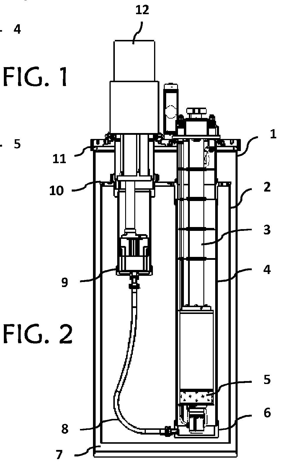
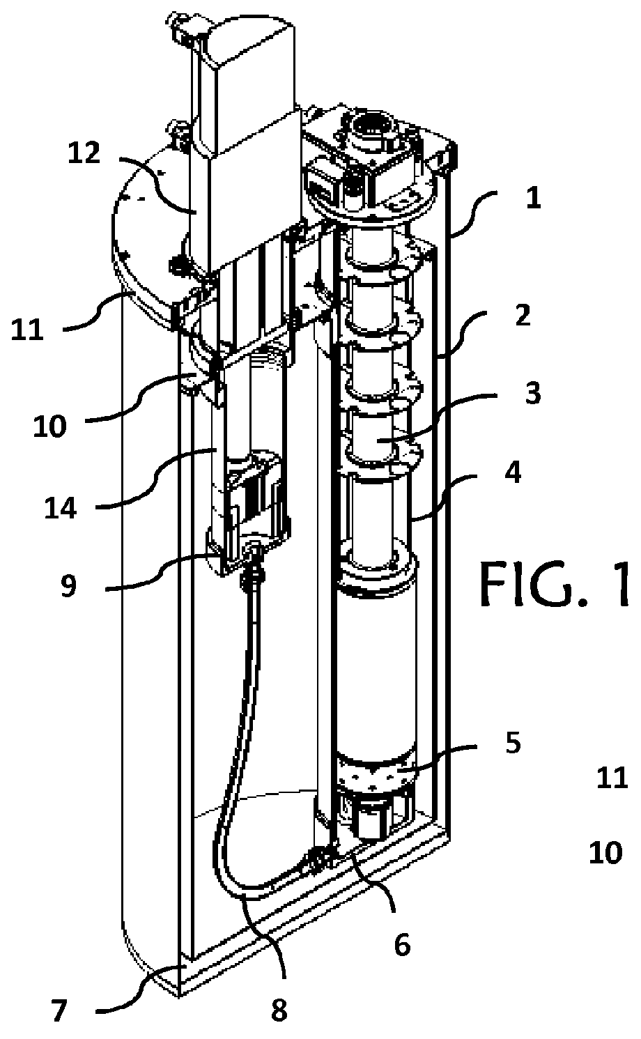
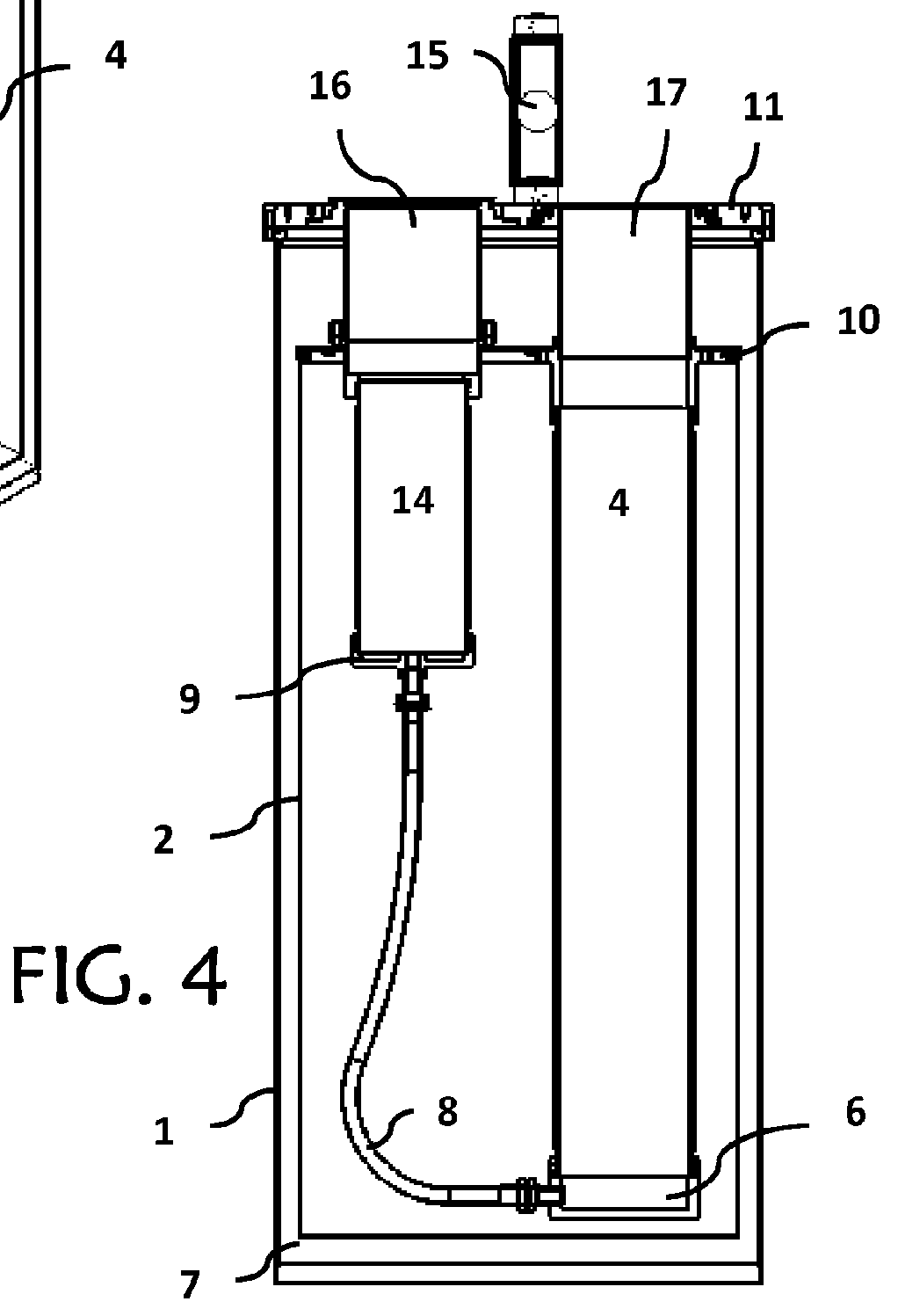
[0039]In a general embodiment of the invention, a Dewar system is provided for containing a cryocooler and a cryostat, wherein a coolant is continually recycled within the Dewar from a gas-phase to a liquid phase. The Dewar system generally includes an inner shell nested within an outer shell, wherein an area between the inner and outer shells is hermetically sealed and substantially evacuated of air to form a vacuum insulated t...


PUM


Abstract

A multi-well helium Dewar is provided for recirculating coolant about a cryostat probe; the Dewar includes a first well containing a first coolant reservoir, and a second well containing a second coolant reservoir. A fluid connection extends between the first and second coolant reservoirs. A low impedance conduit further connects a top end of the second well to the first well. In this regard, the Dewar at least partially contains a cryocooler within the first well and a cryostat probe within the second well. Vibrational noise is reduced by the incorporation of soft mounting components for connecting various features. A thermal shield of the Dewar can be thermally connected to isolated components for additional cooling power and increased efficiency during initialization. A second fluid connection may include a valve attached to a counter-flow heat exchanger for efficiently re-condensing excess gas within the Dewar.

Description

CROSS-REFERENCE TO RELATED APPLICATIONS[0001]This application is a continuation of U.S. Ser. No. 12 / 882,079, filed Sep. 14, 2010; the entire contents of which are hereby incorporated by reference.FIELD OF THE INVENTION[0002]The present invention relates to Dewars for thermally insulating a cryostat and related components; and more particularly to helium gas Dewars for providing an insulated liquid or gaseous Helium environment for cryostats adapted to control the temperature of a region or sample. Other uses include mounting of superconducting devices such as magnets in said Dewars.BACKGROUND OF THE INVENTION[0003]Cryogenic helium flow cryostats have been used for many years to regulate temperature in systems designed to test the physical properties of laboratory specimens. The need for testing physical specimens has increased substantially over the last several years. These systems are designed to characterize the physical properties of various materials under variable measurement ...

Claims


Application Information

Patent Timeline
Patent Type & Authority Applications(United States)
IPC IPC(8): F17C7/02F17C13/02F25B9/00
CPCF25D19/00F25B2400/17
Inventor DIEDERICHS, JOSTSIMMONDS, MICHAEL BANCROFT
Owner QUANTUM DESIGN
Why Eureka
Try Eureka