Systems and methods for delivering electrical energy in the body

a technology of electrical energy and systems, applied in the direction of generators/motors, magnetic properties, therapy, etc., can solve the problems of bone death, large amount of energy stored by cells, surgical procedures for implanting electrodes, etc., to reduce the cost, the effect of minimal invasiveness and minimal surgical time and possible errors

Inactive Publication Date: 2009-03-05
FERRO SOLUTIONS
View PDF25 Cites 47 Cited by
  • Summary
  • Abstract
  • Description
  • Claims
  • Application Information

AI Technical Summary

Benefits of technology

[0024]Thus, in one embodiment the present invention provides a therapy for chronic pain that utilizes one or more miniature ME's as neurostimulators and is minimally invasive. The simple implant procedure results in minimal surgical time and possible error, with associated advantages over known treatments in terms of reduced expense, reduced operating time, single implant surgery, and therapy provided on an as needed basis. Other advantages, inter alia, of the present invention include the system's monitoring and programming capabilities, the power source, storage, and transfer mechanisms, the activation of the device by the patient or clinician, the system's open and closed-loop capabilities, the closed-loop capabilities being coupled with sensing a need for and / or response to treatment, coordinated use of one or more stimulators, and the small size of the stimulator.

Problems solved by technology

Electrical current densities produced by such fields are typically in the range of 10 to 20 μA; 5 μA has been found to be ineffective and currents greater than 20 μA may cause bone death.
Therefore implanted primary cells must store a large amount of energy.
While invasive bone stimulation is highly focused, the disadvantage is that a surgical procedure is required to implant the electrodes and large storage cell.
The problems met in non-invasive electrotherapy include 1) inconvenience, and hence a higher rate of patient non-compliance, due to the external apparatus that is currently used, 2) to get an adequate electric field to the precise location of the fracture using electrodes that are farther from the fracture or where the capacitor plates have a larger area, requires that the electric field fills a larger volume, thus drawing more current and requiring more power, 3) the larger field volume exposes more body tissue to potentially harmful currents, and 4) to sustain continuous field application to the fracture requires that a large electrical apparatus, housing a larger primary cell that produces a greater voltage, be attached to the body near the fracture.
The problems with invasive electrotherapy include 1) the need for surgical procedure and anesthesia to implant the electrodes and primary cell, 2) the need to adjust the location of the implanted electrodes during this surgery so that the field is applied directly across the fracture, and 3) despite the lower power requirements due to the proximity of the electrodes to the fracture site, implantation requires a relatively large implanted battery to provide continuous therapy for 6 to 9 months in order to avoid more frequent surgeries to replace the battery.

Method used


Image

  • Systems and methods for delivering electrical energy in the body
  • Systems and methods for delivering electrical energy in the body
  • Systems and methods for delivering electrical energy in the body

Examples


first embodiment

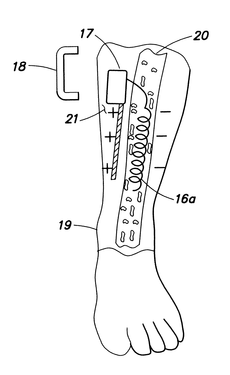
[0201]In the first embodiment shown in FIG. 15, an internally disposed (within the bone 20) coil-like electrode 16a is connected to one electrode of a laminated magneto-electric power receiver 17, the receiver being implanted in soft tissue 21 near the fracture site. The implant 17 includes the ME receiver integrated with a power conditioning chip and a short-term (possibly 1 week) rechargeable cell. Whereas a prior art primary storage cell can typically last up to 9 months, continuously delivering 20 μA at about 1 V, it has a capacity of a few tenths of a Watt-hour (W-h). In contrast, the rechargeable cell used in the present embodiment need only supply about 20 μW for a week, so the rechargeable cell (in implant 17) need only have a capacity of a few milli Watt-hours (mW-h); as a result it can be about 1% of the volume of the prior art implanted cell. The rechargeable cell of the present embodiment has a rate of energy transfer of about 0.3 W using safe AC magnetic field levels; i...

second embodiment

[0202]In the second embodiment shown in FIG. 16, a stabilizing rod 16b implanted in the bone to maintain alignment and provide stabilization during healing also functions an electrode (instead of coil electrode 16a of FIG. 15). The statements made above for FIG. 15, with the exception of the last statement regarding use for vertebral fracture, also apply to FIG. 16. However, because (in FIG. 16) there may be a larger area between the electrodes (based on the length of the fracture), a larger voltage may need to be applied to the electrodes to maintain a constant charge on the electrodes and E field strength at the fracture (see Eq. 1).

[0203]In regard to the third embodiment (FIGS. 17-18), in cases of severe bone fracture there are often metal fastener(s) placed in the bone, or a metal clamp connecting two stabilizing braces along the length and on opposite sides of the bone. The metal fastener(s), e.g., a screw 25 or bolt 26, can be manufactured in two electrically-insulated parts (...


PUM


Abstract

Small implantable magnetostrictive-electroactive (ME) device for delivering electrical energy to surrounding tissue. The wireless ME device is activated by a changing magnetic field from an externally applied alternating magnetic field source. The ME device provides a means for stimulating a nerve, tissue or internal organ with direct electrical current, such as relatively low-level direct current for temporary or as needed therapy. The field source (e.g. small coil antenna) may be a hand-held device or affixed to the wearer's skin, clothing or accessories. The ME implant may be configured as pellets which are small enough to be implanted through a surgical needle. In one embodiment, the wireless energy transmission system can be used for stimulating bone growth.

Description

RELATED APPLICATIONS[0001]This application claims priority to U.S. Provisional Application No. 60 / 976,030 filed Sep. 28, 2007 and is a continuation in-part of U.S. application Ser. No. 11 / 734,181 filed Apr. 11, 2007, which claims the benefit of priority to U.S. Provisional Application No. 60 / 791,004, filed Apr. 11, 2006, and is a continuation-in-part of U.S. application Ser. No. 11 / 652,272, filed Jan. 11, 2007, which claims the benefit of priority to U.S. Provisional Application No. 60 / 758,042, filed Jan. 11, 2006, and U.S. Provisional Application No. 60 / 790,921, filed Apr. 11, 2006, and is a continuation-in-part of U.S. application Ser. No. 10 / 730,355, filed Dec. 8, 2003, which claims the benefit of priority to U.S. Provisional Application No. 60 / 431,487, filed Dec. 9, 2002, the disclosures of which are incorporated herein by reference in their entirety.FIELD OF THE INVENTION[0002]The present invention relates to systems and methods utilizing one or more implantable devices for del...

Claims


Application Information

Patent Timeline
Patent Type & Authority Applications(United States)
IPC IPC(8): A61N1/378
CPCA61N1/326A61N1/3787A61N2/006H02N11/002G01R33/18H02K57/003A61N2/02H02K99/10H10N35/00
Inventor O'HANDLEY, ROBERT C.HUANG, JIANKANGSIMON, JESSEO'HANDLEY, KEVINSUNDRUM, HARIHARAN
Owner FERRO SOLUTIONS
Why Eureka
Try Eureka