[0009] The present invention is directed at providing a venting system that is particularly suited for a foam-in-bag dispensing system which helps avoid or lessen the effect of the numerous drawbacks associated with the prior art systems such as those described above. In so doing, the present invention presents a highly versatile system that provides numerous advantageous features without invoking added complexity and added components, which is a common tendency in the prior art systems, particularly of late.
[0011] The present invention further includes alternate arrangements as in venting devices which utilize an alternate vent formation means as in a heat source (e.g., electric resistance or
high energy light, etc), although a blade device is preferred as it avoids added complexity and is low cost and easy to replace. Alternate combinations include, for example, heated blades or a combination of positioning of the venting devices (e.g., replacing different
cane locations including venting within an inch or two of opposite edges of the film), although the noted “C-fold” only side positioning provides for vent formation relative to a known condition edge (unlike the alternate side which may have a defect during seal formation). Additional alternate arrangement under the present invention include a combination of blade venting with edge seal interruption (e.g., a blade vent
assembly used in conjunction with a system such as the intermittent labyrinth side seam in U.S. Pat. No. 4,999,975 or one of the other interrupted side seam vent arrangements described above) or in conjunction with a
small hole (e.g., spike formed vented film sheet as seen in U.S. Pat. No. 5,794,406). Again, however for the avoidance of complexity and added repair and film feed disruption potential the vent systems described in greater detail below as preferred embodiments are preferable for most vent need environments.
[0012] Some of the features of a preferred embodiment include a blade venting device with a blade mounted inside of its own customized blade housing. A function of the noted blade housing is to provide protection for personnel who
handle the blade during installation or service, and the blade housing can be made of
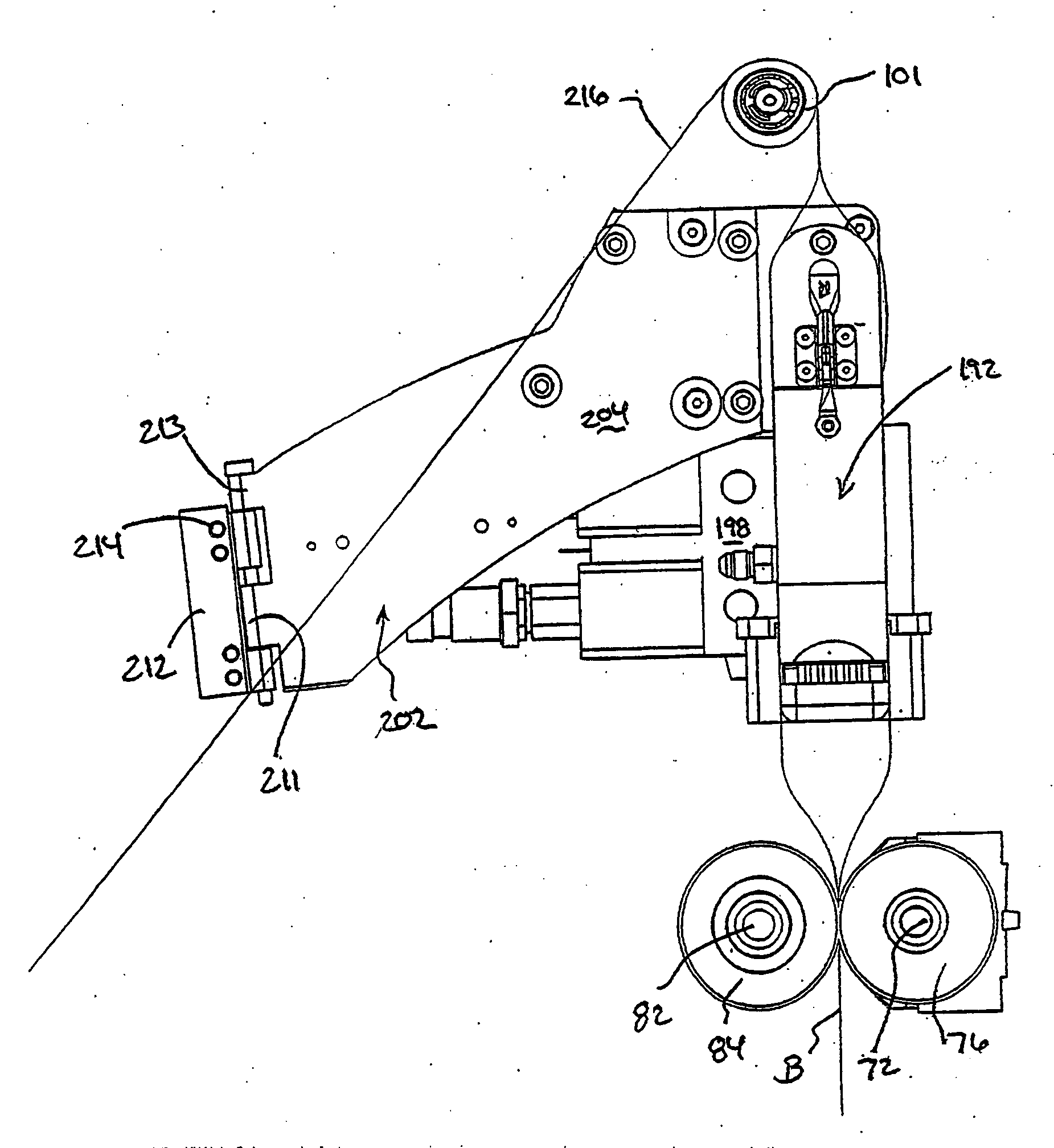
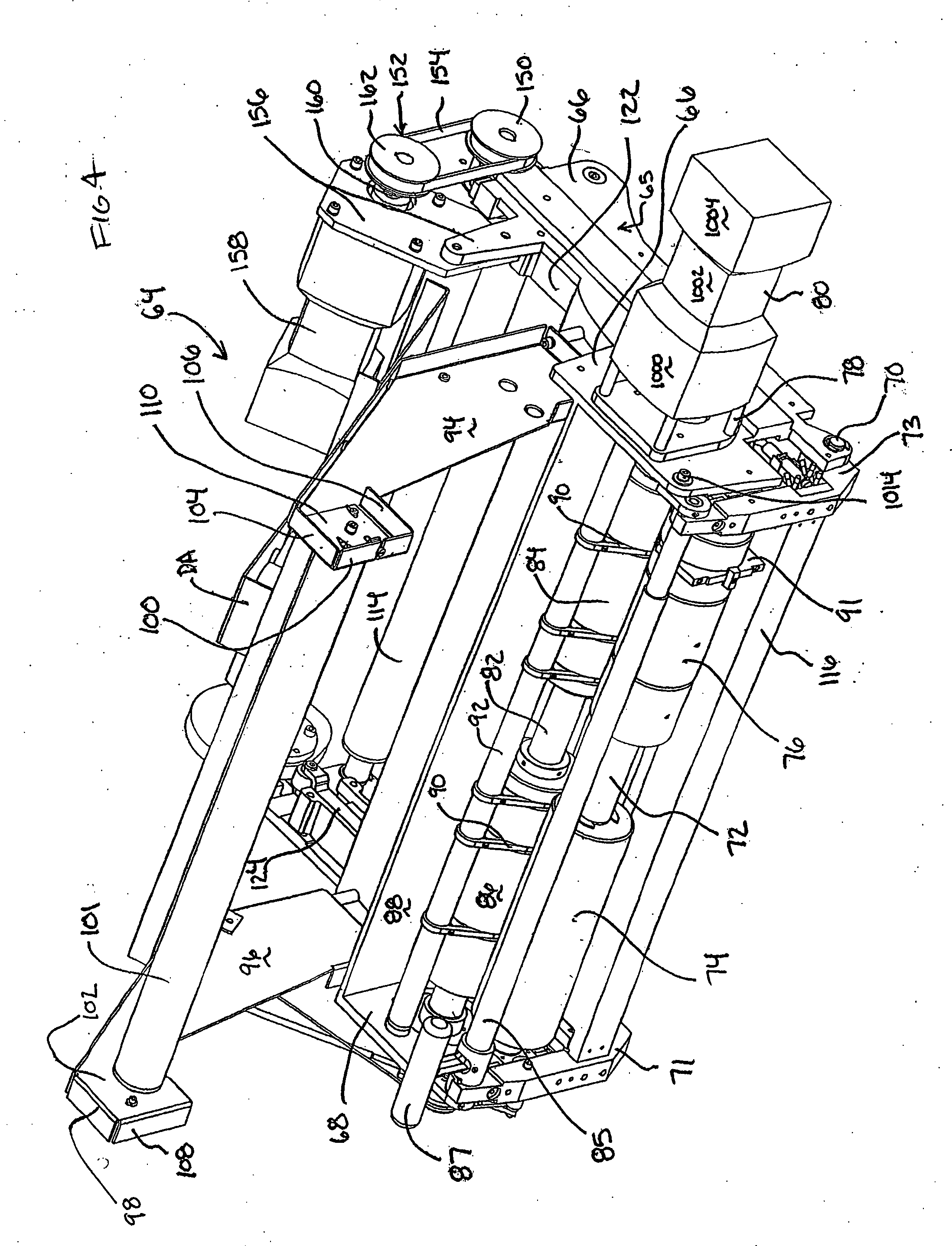
metal or plastic. In a dual blade venting system (preferably two separate housings although an integrated system with a single housing and multiple blades is also featured under the present invention) two blade cartridges are mounted in close proximity to the nip zone between two film drive rollers. For example, a preferred system features blade cartridges that are supported by the
cane support rod that is located above the nip rollers and runs across the front of many machines in the field (although alternate locations are also featured under the present invention as in roller shaft supported locations such as a similar slide and non-rotation arrangement as featured for the edge sealer in the above noted PCT / US2004 / 014423) with a
dual function guide
cane / blade housing arrangement, one blade
cartridge is located in the cane slot on the right side of the rubber nip roller, while another blade
cartridge is located in the cane slot on the left side of the same rubber nip roller (again preferably the one in contact with the C-fold side). In this way, the blade cartridges will perform and anti-wraparound function of the current film canes, upon the canes being replaced by the blade cartridges (in a retrofit situation) or put in what would have been that position in a new
machine manufacture.
[0018] To accommodate for different size bags the venting modules are either adjustably supported or positioned at a location which is universal to different sizes as is the adjacent cane embodiment. For example, in one embodiment the mounting base includes a releasable clamp
assembly as in an over-center latch preferably with a high friction block for contact with the roller support frame back wall that can be readily repositioned along the frame backwall and clamped back into position (again preferably by at a cane replacement location). Thus, with the preferred embodiment of the invention there is an improved venting which reduces the possibility of foam shrinkage and minimize restrictions to foam flow and distribution within the bag. Also the described double blade venting system is easily retrofittable onto any existing foam-in-bag in the field. Also, the
control system to operate the venting knives is relatively easy to implement requiring for most preferred usages simply on / off control of solenoid actuators. Accordingly, there can be avoided relatively
complex control system, such as those required to “
feather” the flow of
electrical current through an electrical
cut wire. In addition, partially with a pivot out
mount base driver support and releasable
cartridge (e.g., a spring or friction lever latch with capture recess assembly as in common with many printer cartridges) the blade holding cartridges will be easy to replace should their blades get dull or damaged. Also, the venting blades are not exposed for undesirable contact to personnel, and are safe to
handle during installation and shipping.
