Valve assemblies

a valve assembly and actuator technology, applied in the direction of valve details, flexible pipes, pipe supports, etc., can solve the problems of limiting the maximum flow rate through the valve, difficulty in providing a face seating valve, and technical difficulties, so as to reduce the force restricting the movement of the armature, reduce the restriction of movement, and slow the opening and/or closing of the valve

Active Publication Date: 2011-09-01
ARTEMIS INTELLIGENT POWER
View PDF15 Cites 11 Cited by
  • Summary
  • Abstract
  • Description
  • Claims
  • Application Information

AI Technical Summary

Benefits of technology

[0051]Preferably, the interior of the valve assembly is configured to minimise restrictions on the movement of the armature from the first position due to a requirement to displace hydraulic fluid. Preferably, movement of the armature is not significantly restricted by the flow of hydraulic fluid through a throttle (e.g. an aperture sized to cause a significant pressure difference to develop across the aperture in use). This reduces forces restricting the armature from moving, slowing opening and / or closing of the valve.
[0052]The secondary valve member typically moves into a secondary valve member receiving volume when the secondary valve moves from the sealing position into the open position. The secondary valve member receiving volume is typically filled with hydraulic fluid in use which is displaced by the movement of the secondary valve member. In contrast to pressure balancing valves, the movement of the armature from the first position typically has no effect on or increases the pressure of hydraulic fluid in the secondary valve member receiving volume. This is advantageous because a reliance on movement of the armature to lower the pressure within the secondary valve member receiving volume can slow the opening of the valve and in particular slow its closing. Preferably the flow of hydraulic fluid into and out of the secondary valve member receiving volume is not throttled. Thus, the valve may close quickly without throttled flow slowing the flow of hydraulic fluid into the secondary valve member receiving volume.

Problems solved by technology

A technical problem which can arise with valve assemblies including electronically actuatable face seating valves (such as poppet valves), for regulating the supply of fluid into the working chamber of a fluid working machine, relates to the requirement to hold the face seating valve open whilst fluid is flowing through the valve.
Thus, it may be necessary to continue to supply a substantial amount of power to the electromagnet to keep the face seating valve open, or this effect may limit the maximum flow rate through the valve.
This is technically difficult because, in a face seating valve, the fluid pressure acts over the seating area to create a large closing force.
Accordingly, it is difficult to provide a face seating valve for regulating the supply of fluid from a high-pressure manifold to a working chamber of a fluid working machine which is capable of opening against a significant pressure differential and which also is also capable of opening quickly (ideally within a few milliseconds) whilst minimizing energy consumption.
In practice it is extremely difficult for this spring to provide enough force to hold the valve open against the Bernoulli and surface friction forces.

Method used


Image

  • Valve assemblies
  • Valve assemblies
  • Valve assemblies

Examples


Embodiment Construction

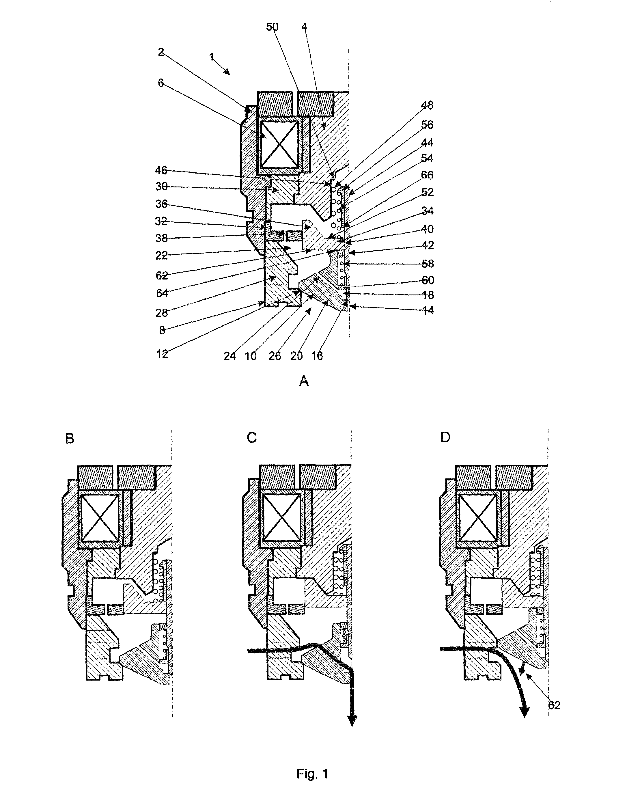
[0065]With reference to FIGS. 1A through 1D, a valve assembly 1 according to the present invention has an annular valve housing 2, made from a magnetically permeable material, which encompasses a body portion 4, also made from a magnetically permeable material. A ring of high reluctance material 30 separates the valve housing from the body portion. An electromagnet 6 is formed around the body portion, within the valve housing. An annular poppet cage 8 extends from the valve housing and encompasses a primary poppet valve head 10, which functions as the primary valve member. The annular poppet cage is made from a magnetically permeable material and the primary poppet valve head is made from a ferromagnetic material, such as steel, and so functions as the ferromagnetic member. A valve seat 12 (functioning as the primary valve seat) is formed by a bevelled transition extending around the interior of the poppet cage. In a closed position, the primary poppet valve head mates with the prim...


PUM


Abstract

An electronically actuatable valve assembly including a valve member comprising a ferromagnetic member, and a magnetic circuit adapted to direct magnetic flux through the ferromagnetic member when the valve member is spaced apart from its valve seat, to hold the primary valve open.

Description

FIELD OF THE INVENTION[0001]The invention relates to the field of electronically actuated valve assemblies for regulating fluid communication between a manifold and a working chamber of a fluid working machine.BACKGROUND TO THE INVENTION[0002]Fluid working machines include fluid-driven and / or fluid-driving machines, such as pumps, motors, and machines which can function as either a pump or as a motor in different operating modes. Although the invention will be illustrated with reference to applications in which the fluid is a liquid, such as a generally incompressible hydraulic liquid, the fluid could alternatively be a gas.[0003]When a fluid working machine operates as a pump, a low pressure manifold typically acts as a net source of fluid and a high pressure manifold typically acts as a net sink for fluid. When a fluid working machine operates as a motor, a high pressure manifold typically acts as a net source of fluid and a low pressure manifold typically acts as a net sink for f...

Claims


Application Information

Patent Timeline
Patent Type & Authority Applications(United States)
IPC IPC(8): F03B11/00F16K31/02
CPCF04B7/0076F16K31/047F16K39/024F16K31/10F16K31/408F16K31/0655Y10T137/8593F16K31/04F16K31/40F16K39/02
Inventor STEIN, UWE BERNHARD PASCALVOLLER, GORDON PAUL
Owner ARTEMIS INTELLIGENT POWER
Why Eureka
Try Eureka