
LED light source

a technology of led light source and led light source, which is applied in the direction of light source, electroluminescent light source, lighting apparatus, etc., to achieve the effects of reducing input-current harmonic distortion, reducing flicker, and increasing power factor

Active Publication Date: 2015-08-18
KONINKLIJKE PHILIPS ELECTRONICS NV
View PDF13 Cites 4 Cited by
  • Summary
  • Abstract
  • Description
  • Claims
  • Application Information

AI Technical Summary

Benefits of technology

The patent is about a LED light source that uses a driver circuit to control the current through the LED loads. By controlling the current, the LED loads can be protected from damage and the light source can be designed with a smaller size and lower power capacity. The LED loads are connected to control strings, which can adjust the current levels to different LED loads, such as controls for color adjustment and flicker reduction. In some embodiments, the LED loads are formed by LED packages, which make the manufacturing process easier. The overall effect of the patent is an LED light source that is cheaper, more efficient, and easier to control.

Problems solved by technology

However, most of the LED packages used in the LED light source are not used in the first LED load.

Method used


Image

  • LED light source
  • LED light source
  • LED light source

Examples


Embodiment Construction

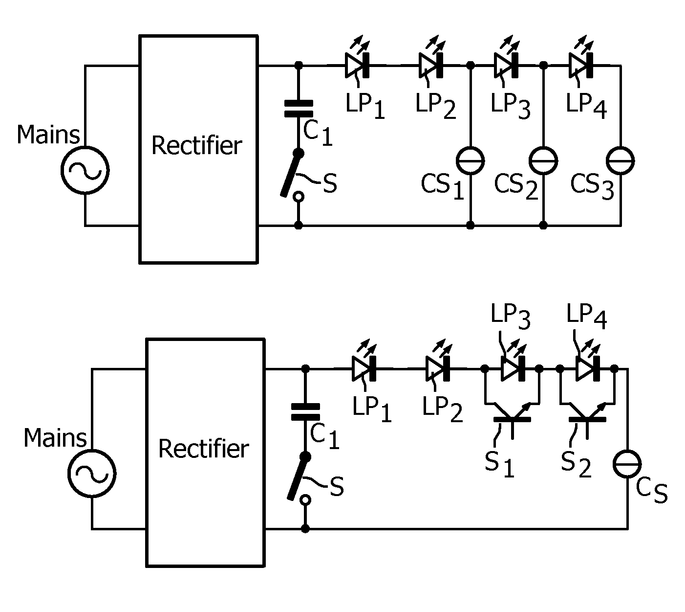
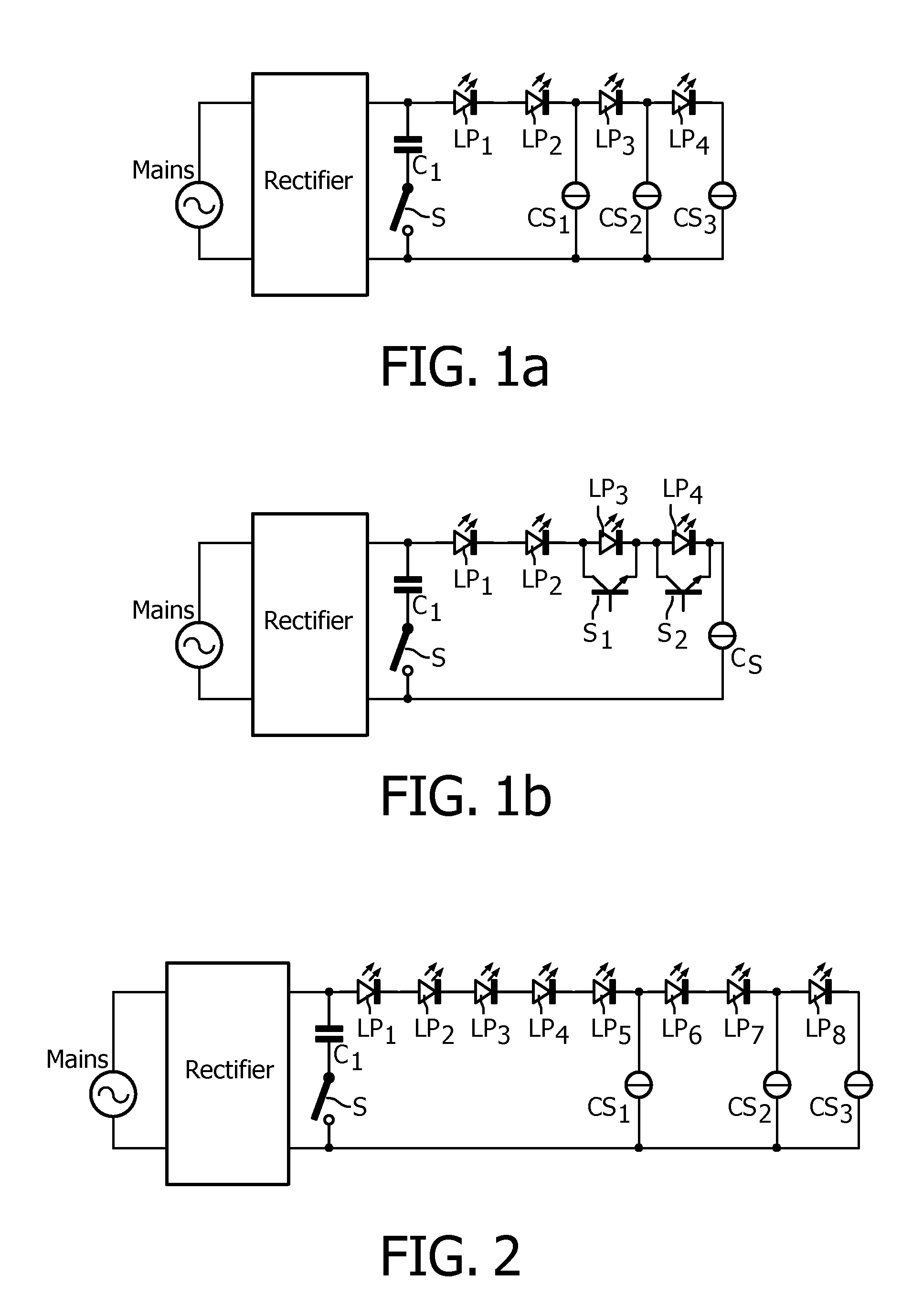
[0041]In FIG. 1a, MAINS is a mains voltage source supplying a low frequency AC supply voltage. The mains voltage source is connected to input terminals of a rectifier. Output terminals of the rectifier are connected by means of a series arrangement of a capacitive element C1 and a switch S, and by means of a series arrangement of a first LED load formed by LED package LP1 and LED package LP2, a second LED load formed by LED package LP3, a third LED load formed by LED package LP4 and a control string formed by switchable current source CS3. A second control string is formed by switchable current source CS2 and connects a cathode of the second LED load to the second output terminal of the rectifier. A third control string is formed by switchable current source CS1 and connects a cathode of the first LED load to the second output terminal of the rectifier. The LED packages LP1-LP4 are identical. The switch S and also the switchable current sources are coupled to control circuitry (not ...


PUM


Abstract

A series arrangement of LED loads (LP1-LP4) is coupled between output terminals of a rectifier having its input terminals coupled to a mains supply supplying a low frequency AC voltage. Control means render the LED loads conductive one by one, when the amplitude of the supply voltage increases, and non-conductive one by one when the amplitude of the supply voltage decreases. The first LED load (LP1, LP2) has a forward voltage that is substantially higher than that of the other LED loads. As a consequence, the LED utilization is comparatively high, thus allowing the LED loads used in the series arrangement to be comparatively cheap.

Description

CROSS-REFERENCE TO PRIOR APPLICATIONS[0001]This application is the U.S. National Phase application under 35 U.S.C. §371 of International Application No. PCT / IB2012 / 051312, filed on Mar. 19, 2012, which claims the benefit of and priority to European Patent Application No. 11160666.1, filed on Mar. 31, 2011. These applications are hereby incorporated by reference herein.FIELD OF THE INVENTION[0002]The invention relates to a LED light source comprising N LED loads that is directly connectable to a supply source supplying a low frequency AC voltage, such as the mains supply.BACKGROUND OF THE INVENTION[0003]Such a LED light source is known from U.S. Pat. No. 7,081,722. The LED loads are LED arrays comprising series arrangements and possibly parallel arrangements of individual LEDs. The known LED light source comprises a rectifier for rectifying the low frequency AC supply voltage. A series arrangement comprising the N LED loads is connected to output terminals of the rectifier. During op...

Claims


Application Information

Patent Timeline
Patent Type & Authority Patents(United States)
IPC IPC(8): H05B37/02H05B33/08H05B44/00
CPCH05B33/083H05B45/48
Inventor KURT, RALPHTAO, HAIMINCREUSEN, MARTINUS PETRUS
Owner KONINKLIJKE PHILIPS ELECTRONICS NV
Learn More