LED light source

a technology of led light source and led light source, which is applied in the direction of light source, electrical apparatus, lighting apparatus, etc., to achieve the effects of reducing input-current harmonic distortion, reducing flicker, and increasing power factor

Active Publication Date: 2014-01-16
KONINKLIJKE PHILIPS ELECTRONICS NV
View PDF2 Cites 4 Cited by
  • Summary
  • Abstract
  • Description
  • Claims
  • Application Information

AI Technical Summary

Benefits of technology

[0012]In other words, because the first LED load carries a lower average current, the worst case to which the LEDs used in the LED light source might be exposed is less severe, so that the die size and the power capacity of the LED packages can be decreased and hence the LED packages are cheaper. It is noted that in order to obtain the same light output, the current through the LED loads needs to be somewhat higher than in the case of a prior art LED light source wherein the forward voltage of the first LED load is lower while the sum of the forward voltages of the LED loads is about the same. However, this increase in current is compensated for by the fact that the LED light source is substantially cheaper.
[0013]Preferably, the forward voltage of the first LED load is at least 100% higher than that of any of the other LED loads. In this latter case the average current through the first LED load is even smaller, so that the LED utilization is increased even more. Moreover, the forward voltage of the first LED load becomes so high that the total number of LED loads comprised in the LED light source can be reduced by 1, with respect to a prior art LED light source wherein the forward voltage of the first LED load is approximately equal to that of each of the other LED loads. This reduction of the number of LED loads means that for instance the number of switchable current sources needed in the LED light source is decreased by one, so that in addition to the higher LED utilization there is also cost saving because fewer components are needed.
[0019]In a second example, the control means comprise N control strings comprising a switchable current source and connecting the cathode of a LED load to the second output terminal of the rectifier. During a time period wherein the first n LED loads are conducting current, only the nth current source is switched on and conducts current. Each of the switchable current sources first of all prevents the current through the LED loads from becoming too high. Furthermore, the current level of each of the switchable current sources can be adjusted to a different value. In the case that for instance different LED loads comprise LEDs of different colour, the colour of the light generated by all the current conducting LED loads together is changed every time a new LED load starts conducting. The contribution of each of these different colours to the average colour of the light perceived by the human eye can be adjusted by adjusting the current level of the switchable current sources. Adjusting the current level of the switchable current sources can also be used to reduce flicker and the stroboscopic effect of the light source, or it can be used to increase the power factor and reduce the input-current harmonic distortion.
[0020]In a preferred embodiment of a light source according to the invention, the LED light source comprises between 3 and 6 LED loads. Generally, when the number of LED loads increases, the ratio between power in the LED loads and the input power of the LED light source increases. However, the amount of circuitry comprised in the control means increases as well, so that the actual number of LED loads is a trade-off between efficiency and cost. The preferred embodiment offers good efficiency and reduced complexity of the control circuit.
[0023]Preferably, the LED loads are formed by one or more LED packages comprising one or more multi-junction LED dies. Use of the packages renders the manufacturing of a LED light source according to the invention comparatively easy. The LED packages preferably have a forward voltage in one of the ranges in the group formed by 24V±5%, 36V±5%, 48V±5% and 72V±5%. The ranges are chosen so that when the low frequency AC supply voltage is the European mains voltage or the North American mains voltage, the LED loads can easily be formed by a number of these packages.
[0028]The switch S is controlled so that the capacitive element is charged during a time period wherein the momentary amplitude of the periodicDC voltage is comparatively high. The voltage across the capacitive element is used as a supply voltage for the LED loads when the momentary amplitude of the periodicDC voltage is comparatively low. In this way, the total amount of current supplied to the LED loads is increased.

Problems solved by technology

However, most of the LED packages used in the LED light source are not used in the first LED load.

Method used


Image

  • LED light source
  • LED light source
  • LED light source

Examples


Embodiment Construction

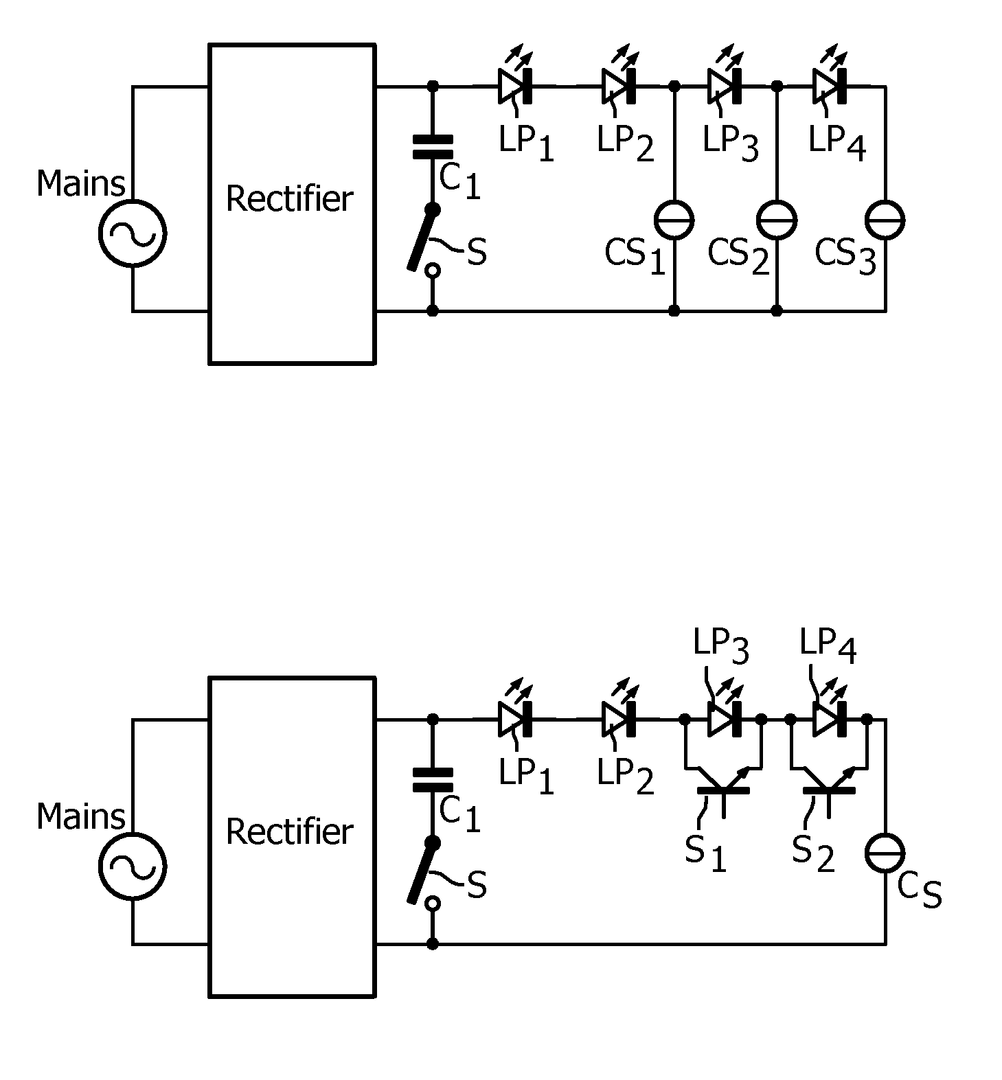
[0038]In FIG. 1a, MAINS is a mains voltage source supplying a low frequency AC supply voltage. The mains voltage source is connected to input terminals of a rectifier. Output terminals of the rectifier are connected by means of a series arrangement of a capacitive element C1 and a switch S, and by means of a series arrangement of a first LED load formed by LED package LP1 and LED package LP2, a second LED load formed by LED package LP3, a third LED load formed by LED package LP4 and a control string formed by switchable current source CS3. A second control string is formed by switchable current source CS2 and connects a cathode of the second LED load to the second output terminal of the rectifier. A third control string is formed by switchable current source CS1 and connects a cathode of the first LED load to the second output terminal of the rectifier. The LED packages LP1-LP4 are identical. The switch S and also the switchable current sources are coupled to control circuitry (not ...


PUM


Abstract

A series arrangement of LED loads (LP1-LP4) is coupled between output terminals of a rectifier having its input terminals coupled to a mains supply supplying a low frequency AC voltage. Control means render the LED loads conductive one by one, when the amplitude of the supply voltage increases, and non-conductive one by one when the amplitude of the supply voltage decreases. The first LED load (LP1, LP2) has a forward voltage that is substantially higher than that of the other LED loads. As a consequence, the LED utilization is comparatively high, thus allowing the LED loads used in the series arrangement to be comparatively cheap.

Description

FIELD OF THE INVENTION[0001]The invention relates to a LED light source comprising N LED loads that is directly connectable to a supply source supplying a low frequency AC voltage, such as the mains supply.BACKGROUND OF THE INVENTION[0002]Such a LED light source is known from U.S. Pat. No. 7,081,722. The LED loads are LED arrays comprising series arrangements and possibly parallel arrangements of individual LEDs. The known LED light source comprises a rectifier for rectifying the low frequency AC supply voltage. A series arrangement comprising the N LED loads is connected to output terminals of the rectifier. During operation, a periodicDC voltage with a frequency 2f and an amplitude varying between zero Volt and a maximum amplitude is present between the output terminals of the rectifier. When the amplitude of the periodicDC voltage is zero Volt, none of the LED loads carries current. When the amplitude of the periodicDC voltage increases, a voltage is reached at which a first LED ...

Claims


Application Information

Patent Timeline
Patent Type & Authority Applications(United States)
IPC IPC(8): H05B33/08H05B44/00
CPCH05B33/083H05B45/48
Inventor KURT, RALPHTAO, HAIMINCREUSEN, MARTINUS PETRUS
Owner KONINKLIJKE PHILIPS ELECTRONICS NV
Why Eureka
Try Eureka