Positive infinitely variable transmission (p-ivt)

a transmission and infinite variable technology, applied in the direction of friction gearings, gearing control, toothed gearings, etc., can solve the problems of too complex or incompetent, wear and power loss, and oscillating output problems, so as to achieve a very rapid speed up, reduce wear and power loss, and reduce the effect of wear

Active Publication Date: 2015-08-27
TANG DUC QUANG
View PDF5 Cites 5 Cited by
  • Summary
  • Abstract
  • Description
  • Claims
  • Application Information

AI Technical Summary

Benefits of technology

[0019]The above method of operation allows the P-IVT to overcome the problem of oscillating output, thereby providing for a smoother and quieter drive. The P-IVT can operate at any speed ratio and allow the speed ratio to be rapidly varied. When incorporated within a vehicle, for example, the P-IVT can be used to connect the engine and the differential while requiring neither a start-up clutch nor a drive-reverse gearing. In operation, the P-IVT allows the engine to speed up very rapidly with a large variation range (from idle to max power speed), helps in improving driving performance and / or reducing the power capacity design of the engine, improving the engines thermal efficiency. Since the engine can rapidly speed up, when the vehicle is cruising, for example, the engine can be allowed to function close to the optimum efficient speed to supply required power, or drop to idle speed when power is no longer needed.
[0020]The above provides vehicles equipped with P-IVT advantages in terms of production cost, weight, gas mileages and driving performance in comparison to vehicles with traditional automatic transmissions and CVT based transmissions.

Problems solved by technology

During operation, the slippages between the belt and the sheaves under high clamping pressure cause wear and power loss.
Nearly all the published PECVTs, when solving the non-integer tooth problem, become too complex or incompetent or develop another problem known as oscillating output problem.
The oscillating output induces to fatigue failure.
However, the embodiments do not have any facility to control the speed ratio between the two drive shafts or the torques applied on the shafts.
As a result they are unable to control over when and how fast the speed ratio changes.

Method used


Image

  • Positive infinitely variable transmission (p-ivt)
  • Positive infinitely variable transmission (p-ivt)
  • Positive infinitely variable transmission (p-ivt)

Examples


Embodiment Construction

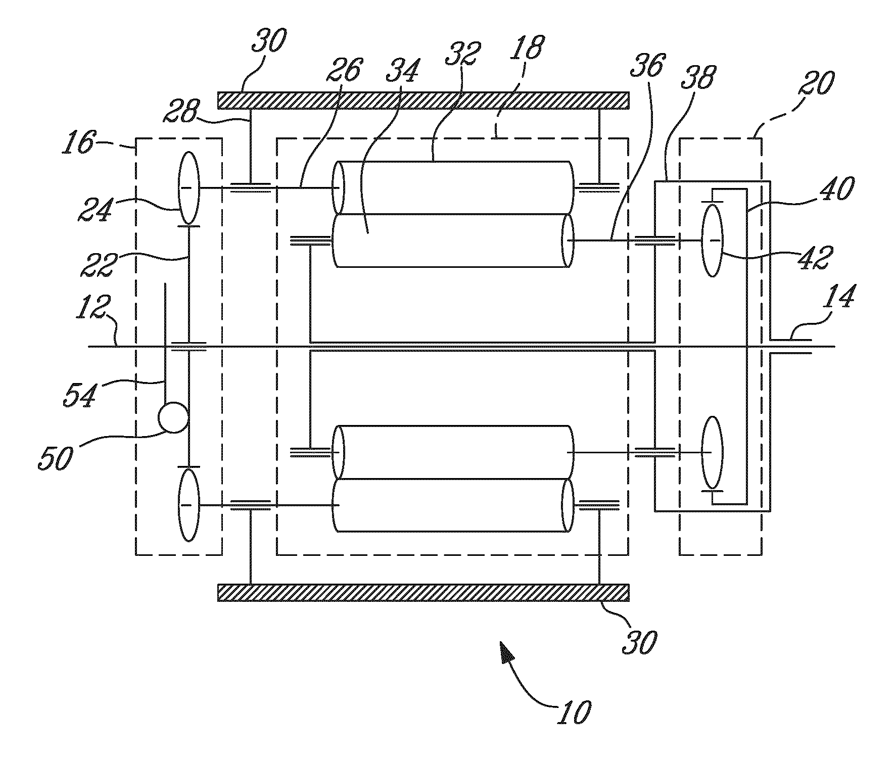
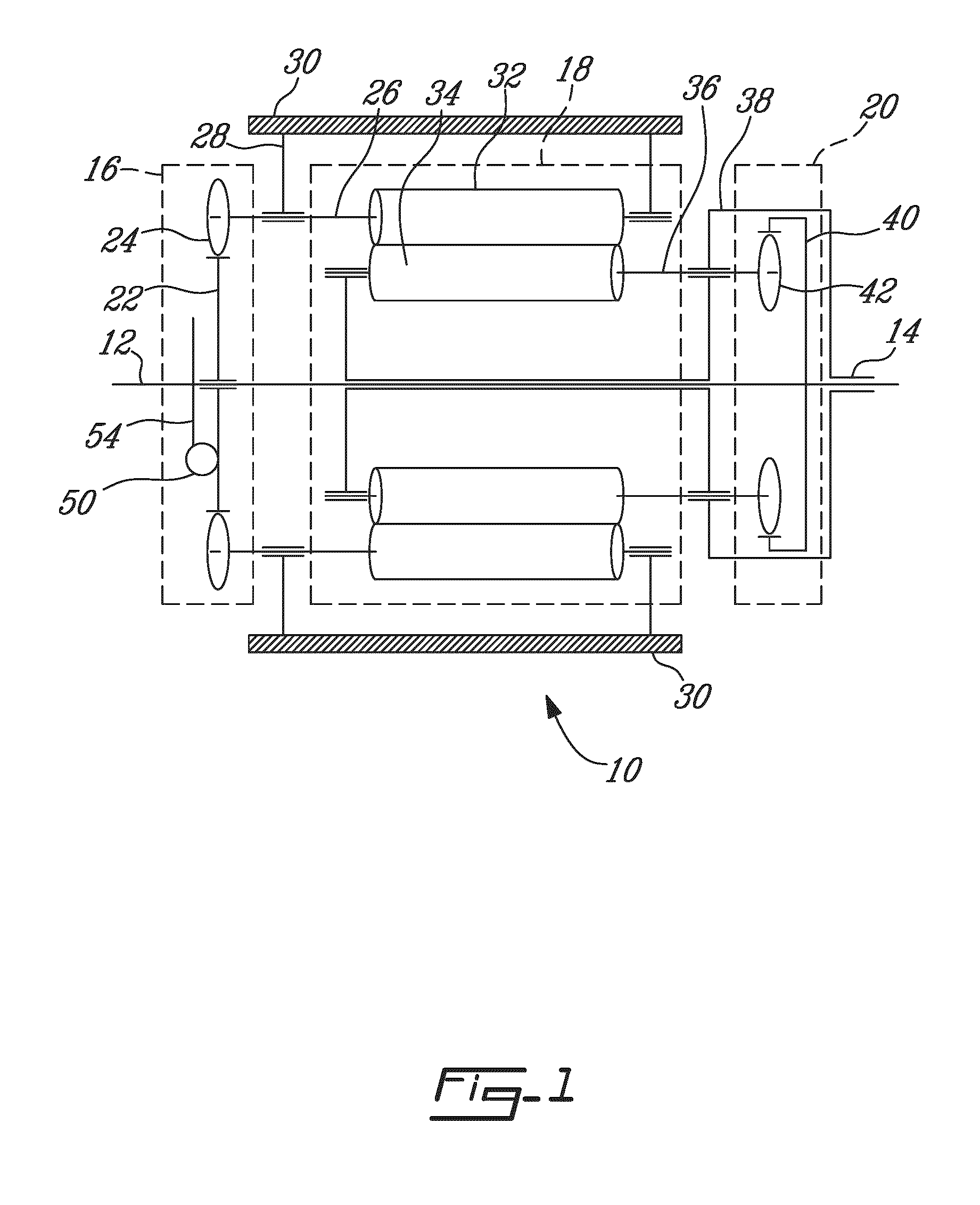
[0037]Referring now to FIG. 1, a P-IVT in accordance with an illustrative embodiment of the present invention and generally referred to by the reference numeral 10, will now be described. The P-IVT 10 comprises a torque transfer mechanism comprising two parts: a mechanical assembly referred to herein as a reactor and a hydrostatic or electrical module referred to as an activator.

[0038]The present invention is illustrated in further detail by the following non-limiting examples.

[0039]Referring to FIG. 1, the reactor comprises a first (input) drive shaft 12 and a second (output) drive shaft 14, a fixed gearset 16, a first planetary gearset 18 and a second planetary gearset 20. The fixed gearset 16 comprises a first gear 22 meshing with a plurality of second gears 24. The first gear 22 is mounted freely on the first drive shaft 12. Each of the plurality of second gears 24 is mounted on one of a first plurality of auxiliary shafts as in 26. The first plurality of auxiliary shafts 26 are...


PUM


Abstract

A positive infinitely variable transmission (P-IVT) is disclosed. The P-IVT comprises a reactor and an activator. The reactor is a differential system, used to transmit power between two drive shafts. The disclosed reactor comprises three gearset comprising non-intersecting and non-parallel gears arranged so that they can be coupled together. The gear ratios and the dimensions of the three gearsets are selected such that the two drive shafts can rotate at any speed ratio. The activator controls the strength and direction of the torques applied to the two drive shafts and enables the transfer of a series of torques through all the gearsets. The strengths and directions of the torques applied on the two drive shafts are controlled through the pressure control unit and the switching valve.

Description

FIELD OF THE INVENTION[0001]The present invention relates to a positive infinitely variable transmission (P-IVT). In particular, the present invention relates to a positive continuously variable transmission (CVT) typically for use within both automobiles and stationary machines. More particularly, the present invention relates to positive engagement CVT, the CVT using positively engaged members, such as gear teeth, to transmit power.BACKGROUND OF THE INVENTION[0002]Continuously Variable Transmission (CVT) provide a variable speed ratio to maintain an optimal match between the power demand and engine speed, which improves engine efficiency, thereby reducing the fuel consumption and gas emissions.[0003]The most common forms of CVT in use today are V-Belt CVTs. V-Belt CVTs are frictional drives that transmit power through fictional forces. They require large effective radiuses, high belt / pulleys clamping pressure and special transmission fluids in order to provide for sufficient drivi...

Claims


Application Information

Patent Timeline
Patent Type & Authority Applications(United States)
IPC IPC(8): F16H15/48F16H15/50F16H61/664F16H61/66
CPCF16H15/48F16H61/664F16H15/50F16H61/66F16H61/66272F16H3/76
Inventor TANG, DUC QUANG
Owner TANG DUC QUANG
Why Eureka
Try Eureka