
Ratchet mechanism

a ratchet and mechanism technology, applied in the field of hand-held ratchets, can solve the problems of complex internal ratchet mechanisms of conventional powered ratchet drive wrenches, many parts interacting with one another, and compulsion to fashion elaborate, interactive components, etc., to achieve the effect of small overall wrench and affordable manufacturing

Active Publication Date: 2015-06-23
IL7
View PDF44 Cites 3 Cited by
  • Summary
  • Abstract
  • Description
  • Claims
  • Application Information

AI Technical Summary

Benefits of technology

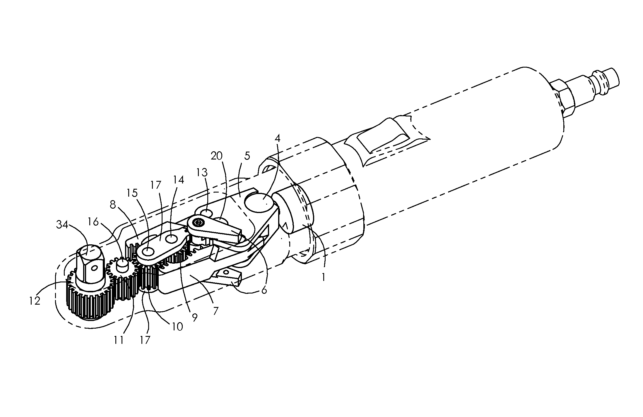
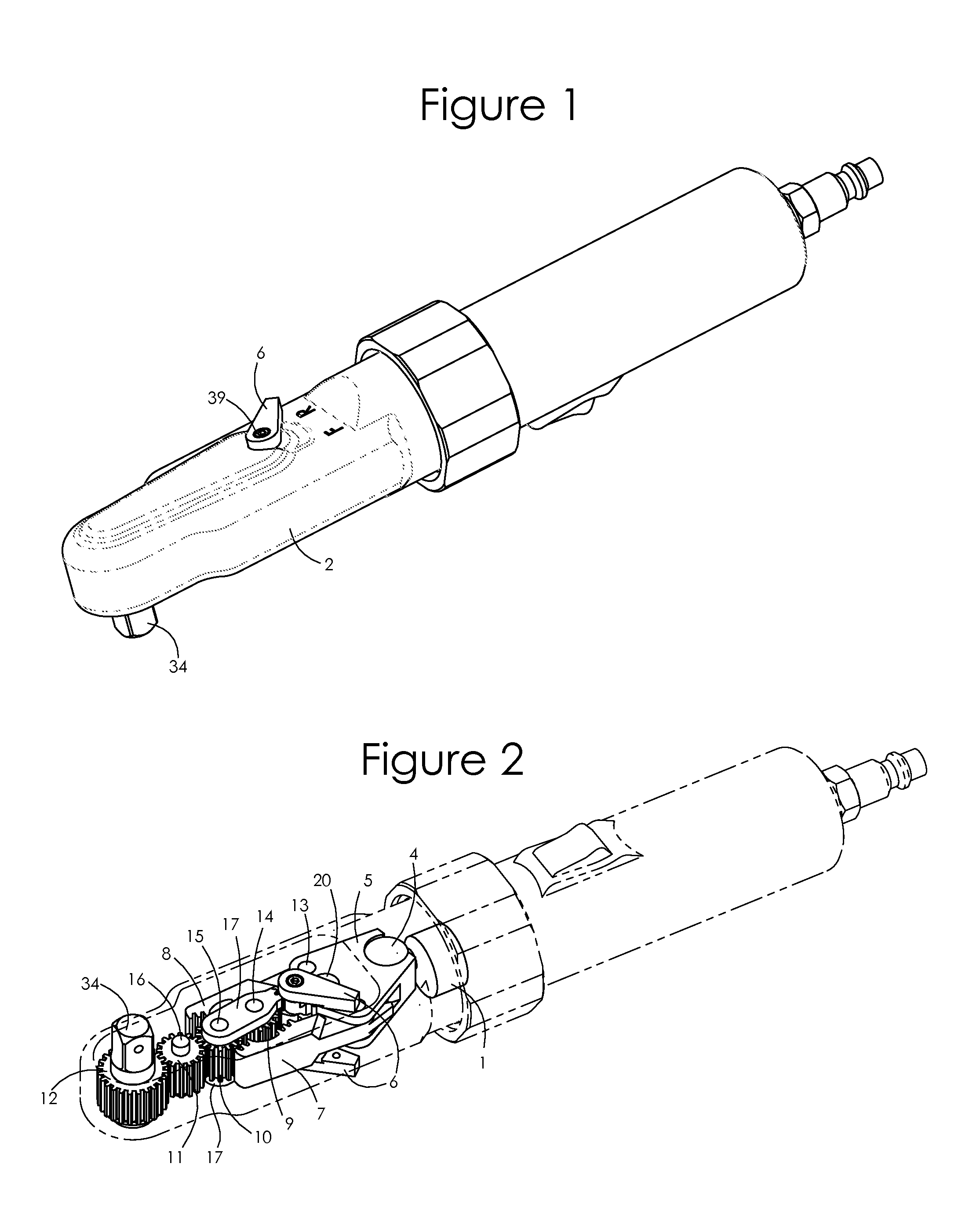
[0010]Among the several objects and features of the present invention may be noted the provision of a ratchet drive wrench which utilizes the full power output of the driving transmission, whether powered pneumatically, hydraulically, electrically or otherwise; the provision of such a wrench which allows for a smaller overall wrench size for access into small spaces; the provision of such a wrench which allows for a suitable balance of output speed, torque and size such that power ratchets, particularly cordless battery powered tools, are more viable; and the provision of such a wrench which may be manufactured inexpensively.
[0015]Ratchets are often used in very confined spaces such as deep inside automotive engine compartments. Since the user can configure the tool to have a reverse lever on the housing side, the cover plate side, or both, the reverse levers being removable, they have considerably more utility with this tool in that the reverse lever is more accessible by either being on both sides or by being on the side of the tool where there is better access for their given circumstances, or the reverse lever or levers can be removed completely to streamline the tool for access into restricted spaces.
[0017]A further advantage of this invention is the greater access to the confined spaces within which such ratchets are typically used. By virtue of its small and smooth head design and further with its reverse actuator remotely located from the output member the tool is better suited to tight spaces and less prone to snagging on wires, belts and hoses typically encountered in tight engine compartments.

Problems solved by technology

Despite the simplicity of the concept behind a powered ratchet drive wrench, the internal ratchet mechanisms of conventional powered ratchet drive wrenches are complex and require many parts interacting with one another.
For instance, wrenches traditionally require complex mechanisms for ensuring that the output member of the wrench does not rotate counter the desired direction during wrench use.
These mechanisms often include multiple parts that serve the limited purpose of inhibiting counter-rotation of the output member.
Similarly, size and space limitations of the wrench often compel the fashioning of elaborate, interactive components.
One difficulty in the fashioning of such a wrench is providing an output member that may rotate in both directions, yet will not rotate opposite the desired direction during the requisite ratcheting retraction stroke between subsequent pawl engagements.
However, this drag is a frictional force that resists motion and is always present, even when counter-rotation is not needed and the pawl is driving the output member.
Thus, some of the tool's output is diminished by having to overcome this parasitic friction.
Typically, those wrenches include frictional pressure washers for impeding counter-rotation of the output member, while other configurations incorporate stop mechanisms of increased complexity and cost.

Method used


Image

  • Ratchet mechanism
  • Ratchet mechanism
  • Ratchet mechanism

Examples


second embodiment

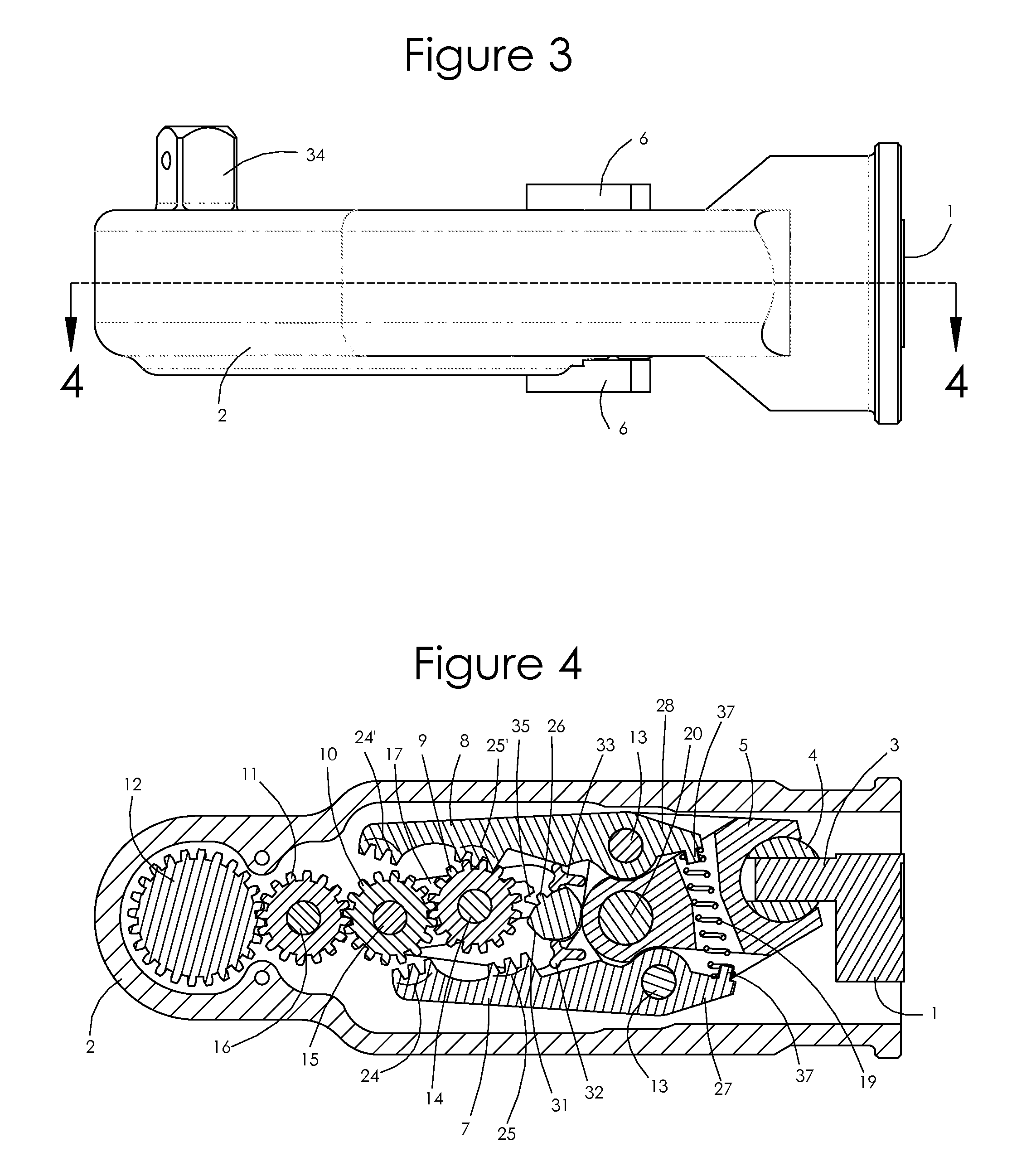
[0042]FIG. 8 illustrates the ratchet mechanism. This embodiment differs from the preferred embodiment in that there is no second stationary intermediate drive member. Instead, in this embodiment the first stationary intermediate drive member 10 engages directly with stationary drive member 12, such that a clockwise rotation of the movable intermediate drive member 9 results in counterclockwise rotation of first stationary intermediate drive member 10 and clockwise rotation of the stationary drive member 12 and, with the movable intermediate drive member 9 repositioned for reversing the output, counterclockwise rotation of the movable intermediate drive member 9 results in clockwise rotation of first stationary intermediate drive member 10 and counterclockwise rotation of the stationary drive member 12. As with the preferred embodiment, reversal of the rotation direction is accomplished by re-positioning the movable intermediate drive member 9 relative to the pawls 7 and 8.

third embodiment

[0043]FIGS. 9 and 10 illustrate the ratchet mechanism. In this embodiment there is neither a first stationary intermediate drive member nor a second stationary intermediate drive member. Instead, the movable intermediate drive member 9 engages directly with the stationary drive member 12, and the proximal toothed engagement sections 25 and 25′ of the pawls 7 and 8 engage directly with the movable intermediate drive member 9 and the distal toothed engagement sections 24 and 24′ engage directly with stationary drive member 12. For clockwise rotation of the stationary drive member 12 and anvil 34, as shown in FIGS. 9a-c, movement of the first pawl 7 in the engaged driving (distal) direction directly rotates stationary drive member 12. Movement of the second pawl 8 in the engaged driving (distal) direction, FIGS. 9d-f, rotates movable intermediate drive member 9 in the counterclockwise direction, which in turn rotates stationary drive member 12 in the clockwise direction. As with the pr...

fourth embodiment

[0044]the ratchet mechanism is shown in FIGS. 11a-b. In this embodiment the ratchet comprises a stationary drive member 12, a first movable intermediate drive member 22 and a second movable intermediate drive member 23, with both the paired movable intermediate drive members 22 and 23 mounted to a pivoting or rotating reverse plate 21 via their respective drive member pins 14 and 15. The first and second movable intermediate drive members 22 and 23 are always engaged with each other during the driving operation. In a first position for clockwise rotation of the stationary drive member 12, as shown in FIG. 11a, the distal toothed engagement section 24 of the first pawl 7 engages the first movable intermediate drive member 22 to rotate it clockwise as the first pawl 7 is extended in the distal direction. The first movable intermediate drive member 22, which is not engaged with the stationary drive member 12, turns the second movable intermediate drive member 23 counterclockwise. The s...


PUM


Abstract

A ratchet mechanism having a plurality of interconnected rotating drive members having teeth, one of the drive members being a stationary drive member and another of the drive members being a movable intermediate drive member, a first pawl member and a second pawl member movable in alternating reciprocating manner, wherein the stationary drive member is alternatingly rotated in a single direction by movement of the pawl members.

Description

BACKGROUND OF THE INVENTION[0001]The invention generally relates to a mechanism incorporated into a handheld power tool that increases functionality or ease of usage. Principally, the invention relates to handheld ratchets driven by pneumatic, electric, hydraulic or manual power sources. More predominantly, this invention relates to a device that applies torque to a rotary fastener to tighten or loosen or otherwise adjust it by turning. In particular, the device utilizes a plurality of toothed engagements to more rapidly impart this torque.[0002]Ratchets are generally known and used as handheld power tools in a wide variety of industries such as automotive repair and manufacturing operations. Ratchets are often energized by pneumatic motors or electric motors powered via line voltage or by way of battery. Increasing the output speed or torque of such ratchets and / or reducing the size of such ratchets will result in several benefits to society.[0003]This invention generally relates t...

Claims


Application Information

Patent Timeline
Patent Type & Authority Patents(United States)
IPC IPC(8): B25B21/00B25B13/46
CPCB25B21/004B25B13/467
Inventor DOHOGNE, DENNIS A.
Owner IL7
Learn More