Ratchet Mechanism
- Summary
- Abstract
- Description
- Claims
- Application Information
AI Technical Summary
Benefits of technology
Problems solved by technology
Method used
Image
Examples
second embodiment
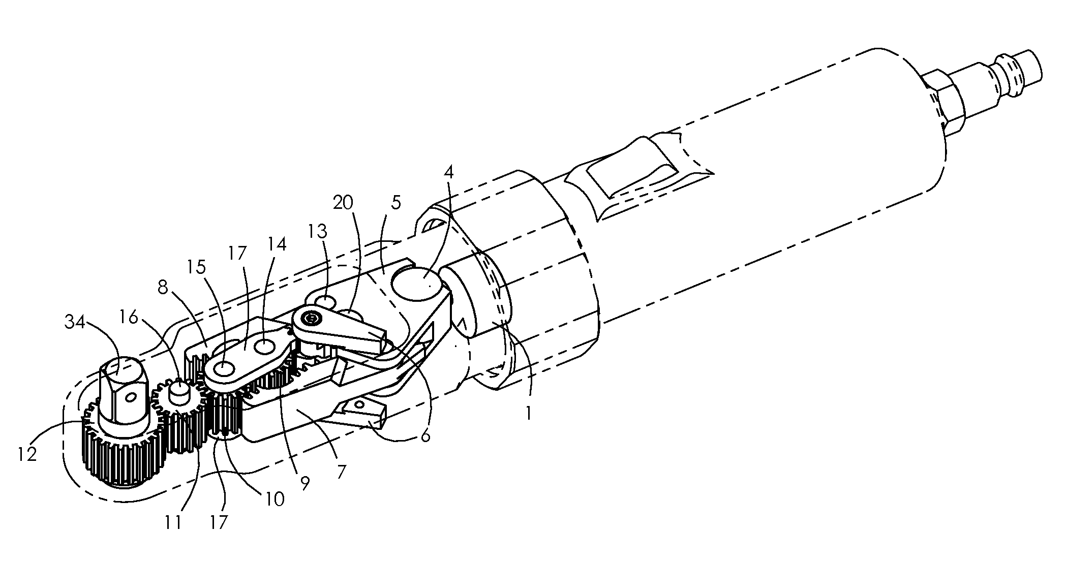
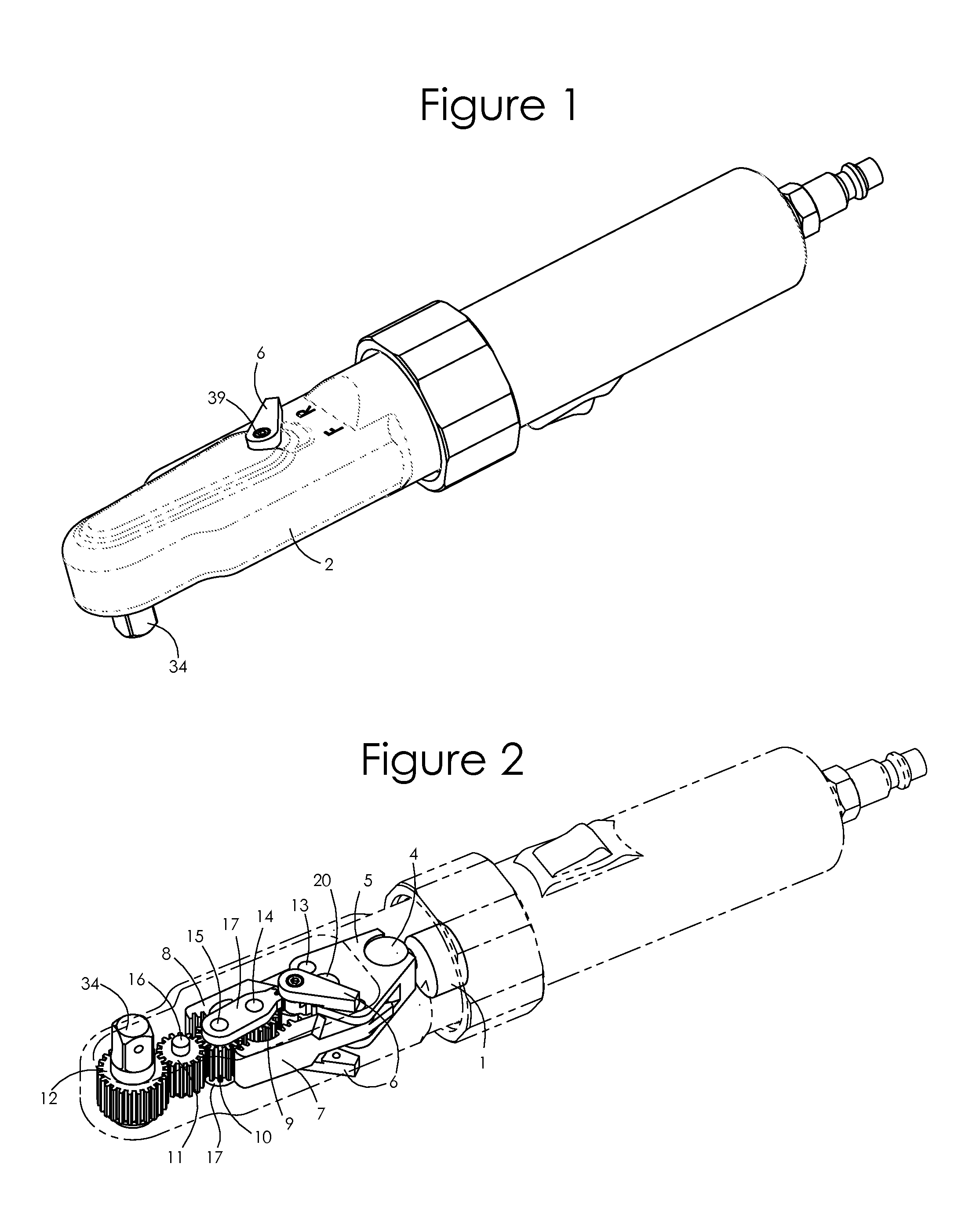
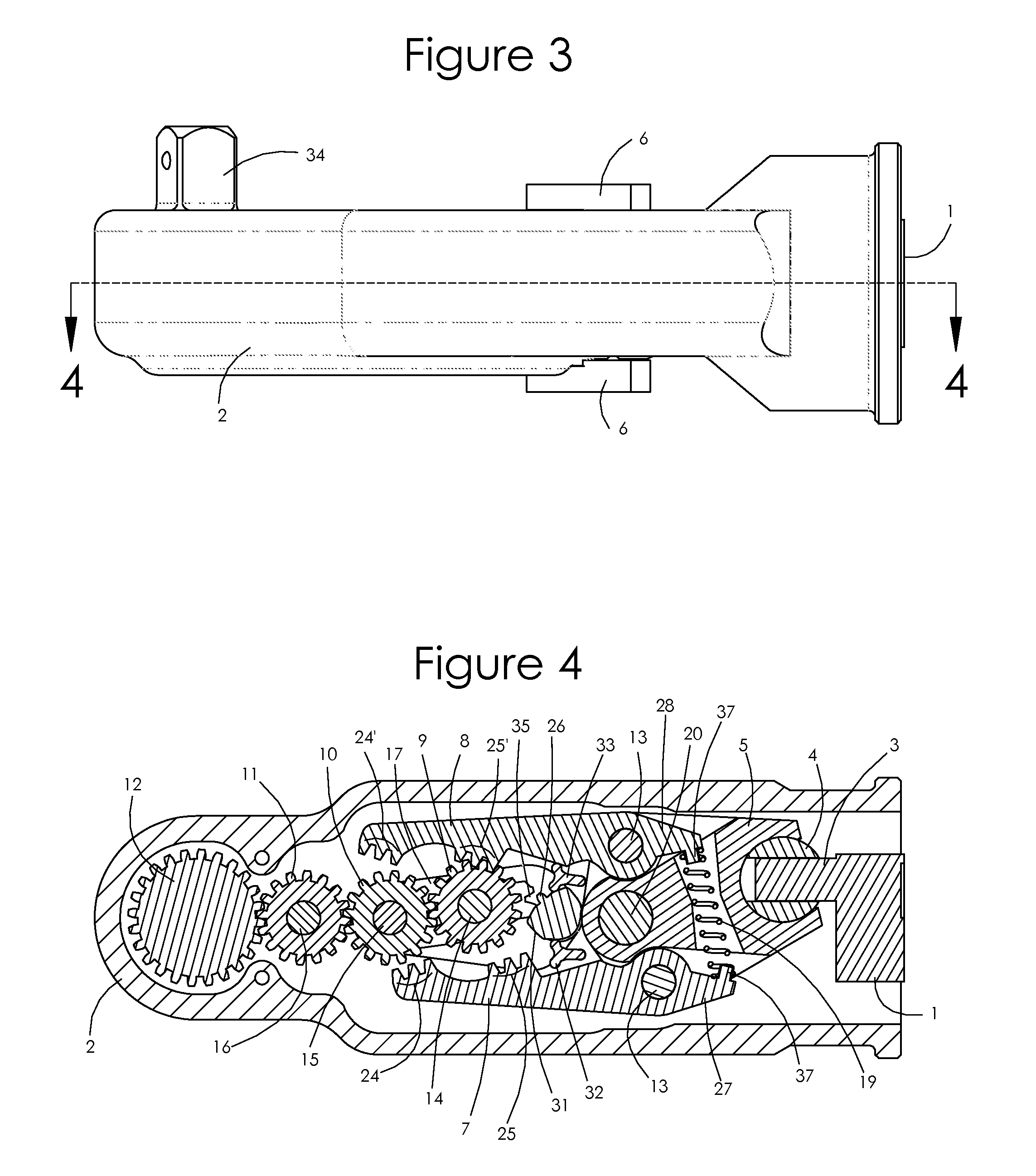
[0042]FIG. 8 illustrates the ratchet mechanism. This embodiment differs from the preferred embodiment in that there is no second stationary intermediate drive member. Instead, in this embodiment the first stationary intermediate drive member 10 engages directly with stationary drive member 12, such that a clockwise rotation of the movable intermediate drive member 9 results in counterclockwise rotation of first stationary intermediate drive member 10 and clockwise rotation of the stationary drive member 12 and, with the movable intermediate drive member 9 repositioned for reversing the output, counterclockwise rotation of the movable intermediate drive member 9 results in clockwise rotation of first stationary intermediate drive member 10 and counterclockwise rotation of the stationary drive member 12. As with the preferred embodiment, reversal of the rotation direction is accomplished by re-positioning the movable intermediate drive member 9 relative to the pawls 7 and 8.
third embodiment
[0043]FIGS. 9 and 10 illustrate the ratchet mechanism. In this embodiment there is neither a first stationary intermediate drive member nor a second stationary intermediate drive member. Instead, the movable intermediate drive member 9 engages directly with the stationary drive member 12, and the proximal toothed engagement sections 25 and 25′ of the pawls 7 and 8 engage directly with the movable intermediate drive member 9 and the distal toothed engagement sections 24 and 24′ engage directly with stationary drive member 12. For clockwise rotation of the stationary drive member 12 and anvil 34, as shown in FIGS. 9a-c, movement of the first pawl 7 in the engaged driving (distal) direction directly rotates stationary drive member 12. Movement of the second pawl 8 in the engaged driving (distal) direction, FIGS. 9d-f, rotates movable intermediate drive member 9 in the counterclockwise direction, which in turn rotates stationary drive member 12 in the clockwise direction. As with the pr...
fourth embodiment
[0044]the ratchet mechanism is shown in FIGS. 11a-b. In this embodiment the ratchet comprises a stationary drive member 12, a first movable intermediate drive member 22 and a second movable intermediate drive member 23, with both the paired movable intermediate drive members 22 and 23 mounted to a pivoting or rotating reverse plate 21 via their respective drive member pins 14 and 15. The first and second movable intermediate drive members 22 and 23 are always engaged with each other during the driving operation. In a first position for clockwise rotation of the stationary drive member 12, as shown in FIG. 11a, the distal toothed engagement section 24 of the first pawl 7 engages the first movable intermediate drive member 22 to rotate it clockwise as the first pawl 7 is extended in the distal direction. The first movable intermediate drive member 22, which is not engaged with the stationary drive member 12, turns the second movable intermediate drive member 23 counterclockwise. The s...
PUM
 Abstract
Description
Claims
Application Information
 - R&D
- Intellectual Property
- Life Sciences
- Materials
- Tech Scout
- Unparalleled Data Quality
- Higher Quality Content
- 60% Fewer Hallucinations
Browse by: Latest US Patents, China's latest patents, Technical Efficacy Thesaurus, Application Domain, Technology Topic, Popular Technical Reports.
© 2025 PatSnap. All rights reserved.Legal|Privacy policy|Modern Slavery Act Transparency Statement|Sitemap|About US| Contact US: help@patsnap.com


